13. Protected Model Maintenance Part 2: Maintenance
204
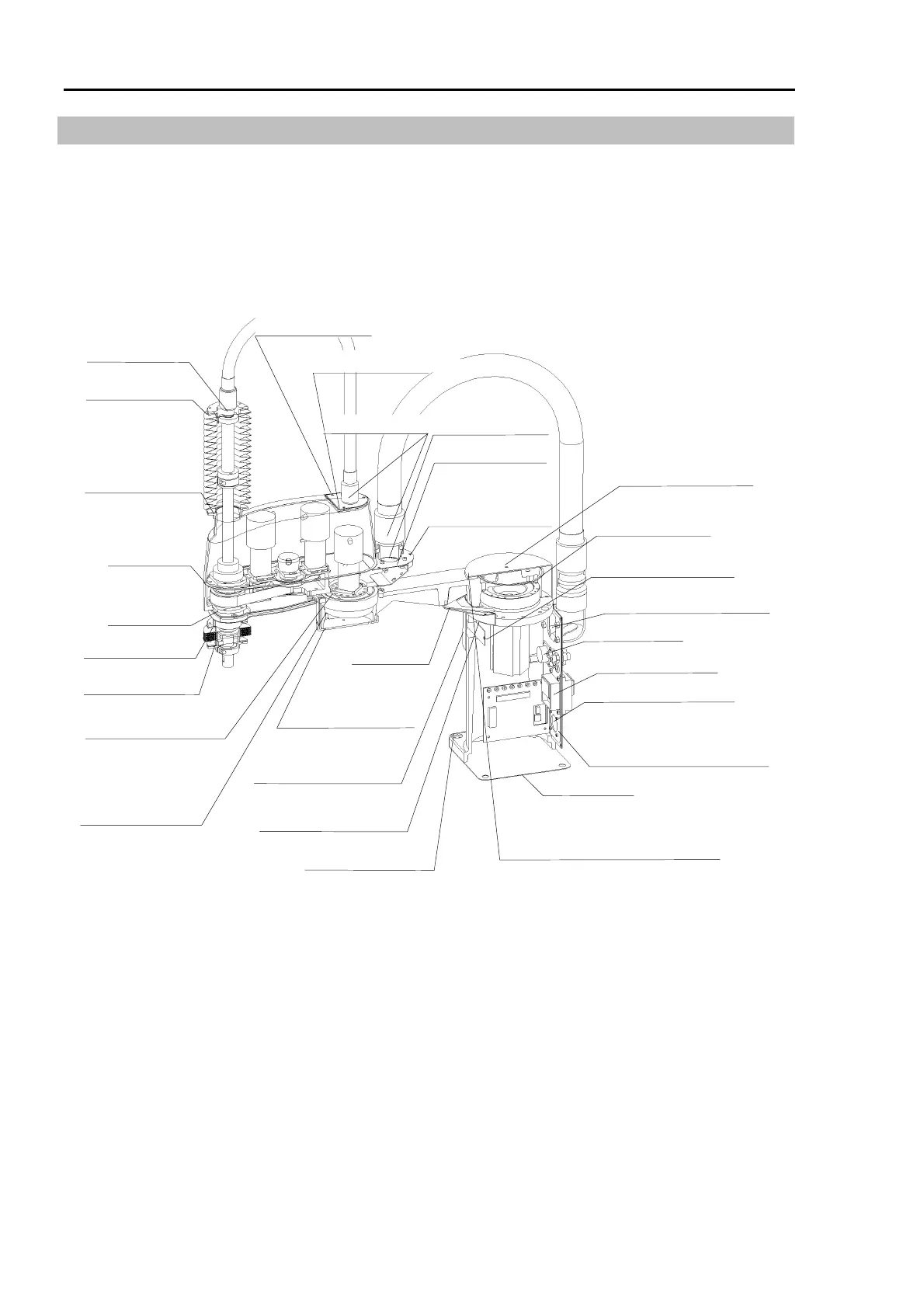
13.2 Sealing the Manipulator
The following figure shows all parts of the manipulator that must be sealed to prevent
moisture and dust. The figure also specifies the type of sealing for each part as types A, B,
C, and D.
If you break any of the seals, be sure to restore all sealing and air tightness after you finish
the maintenance operation.
Duct plate : D
Base plate : D
Maintenance plate : D
User plate
:
A+D
Receptacle : D
Cable seal box : D
Cable elbow fitting
:
C+D
Upper bellows : C
Upper bellows : C
Duct joint
:
B+D
Arm top
cover
:
A+D
Base connector plate
:
A+D
Joint #1 cover : A
Waterproof cover 2
:
watertight washers
Duct joint
:
B+D
Arm bottom
cover
:
A+D
Flange of Joint #1
reduction gear unit : C
Lower bellows : C
Lower bellows : C
Duct rotation : C
Flange of Joint #2
reduction gear unit: C
Bearing surface of
bolts for duct
plate : D
Bearing surface of
bolts for user plate
:
D
Bearing surface of
bolts for waterproof
cover3 : D
Watertight washers
Between waterproof cover 2 and
upper surface of Arm #1 : D
Arm 1# bottom
cover : D
Bearing surface of bolts
for waterproof cover 1:
D+ watertight washers
Encoder reset cover : C
Between Joint #2
reduction gear and
the arm #2 : C(ES)
D(EL)
 Loading...


