3. Replacing the Cable Unit Part 2: Maintenance
98
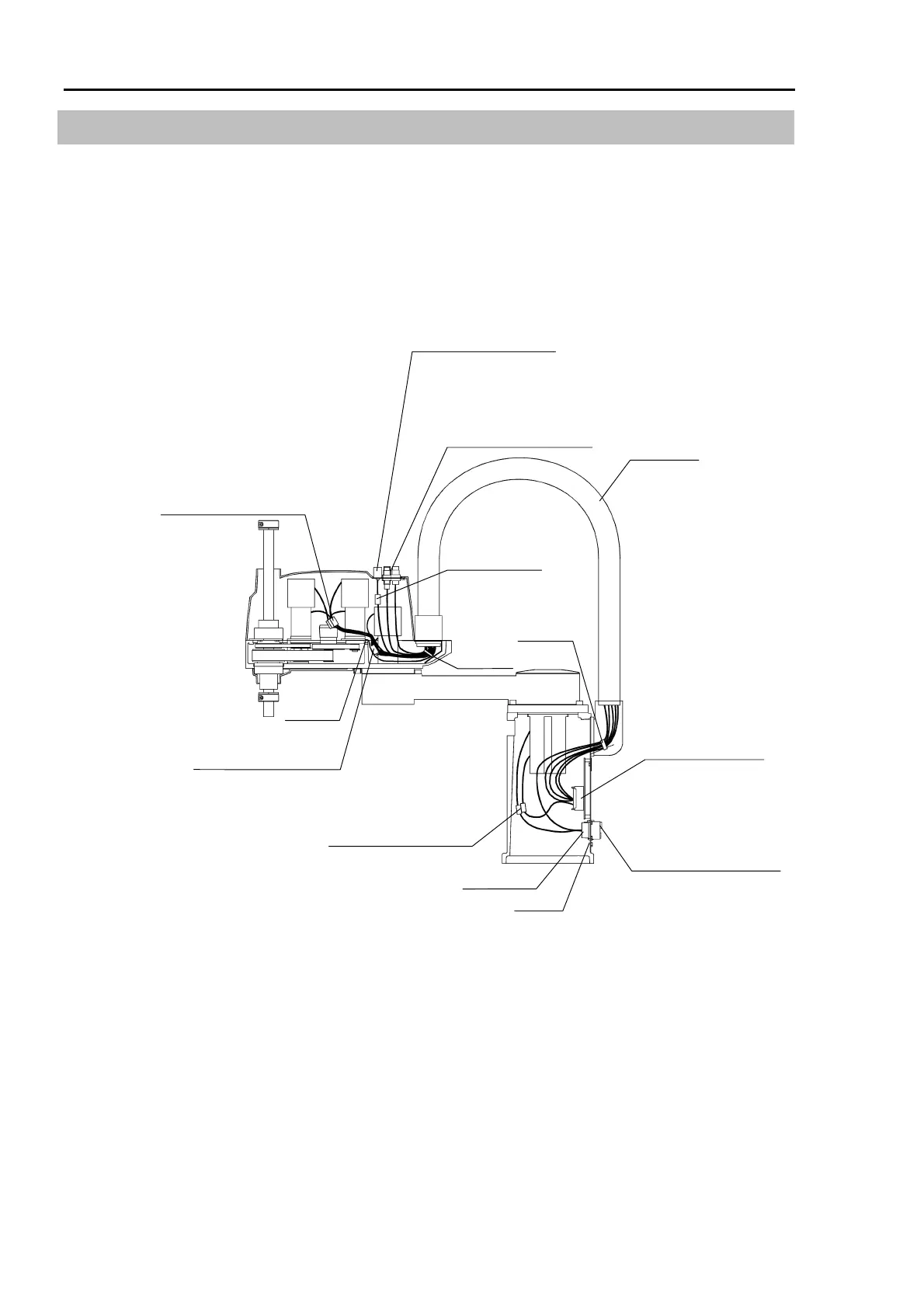
3.2 Wiring Schematic 1
To remove the cable unit, remove the connectors in the arm top cover and base. These
connectors are connected as shown in the figure below. For more information, refer to the
next page and the wiring list in 4. Connector Pin Assignments.
* If the manipulator is a Protected model, refer to chapter 13. Protected Model
Maintenance.
Wire tie
Ground
Ground
Receptacle
D-sub connector X53
Cable unit
Joint #1 Power X110
Joint #1 Signal X11
Signal connectors
Joint #1 X10
Joint #2 X20
Joint #3 X30
Joint #4 X40
User connector X50
Joint #3 Power X131
Joint #3 Signal X31
Joint #3 Brake X32
Joint #3 Brake
release switch X33
Joint #4 Power X141
Joint #4 Signal X41
Fitting for φ 6 tube (×2)
Fitting for φ 4 tube (×1)
White fitting : Blue tube
Black fitting : Black tube
Fitting for φ 6 tube (×2)
Fitting for φ 4 tube (×1)
White fitting : blue tube
Black fitting : black tube
Wire tie
User connectors
X51, X52
Joint #2 Power X121
Joint #2 Signal X21