12. Protected Model Part 1: Setup & Operation
76
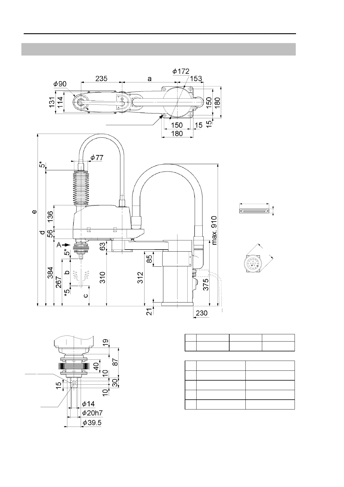
12.5 External dimensions
ES series Protected model [unit : mm]
(*) indicates the stroke margin
by mechanical stop.
Space for cables
or more
Bellows diameter
Waterproof cover 1 diameter
Flange
diameter
Signal cable connector
Power cable connector
50
65
12
Ф4-10 Through hole
ES45*P ES55*P ES65*P
a 215 315 415
ES**1P ES**3P
b
150 300
c 117 -33
d
789 939
e
980
1130
Through hole
Shaft diameter
φ4, 90°
Conical hole
Flat cut
1 mm
(Calibration point position of Joint #3 & #4)
View A detail
Mechanical stop
diameter
The shaft of ES**3P will reach lower tha
the bottom of the manipulator base when it is
fully lowered. Pay attention to it when yo
design a layout.
 Loading...


