2. Installation Requirements Part 1: Setup & Operation
6
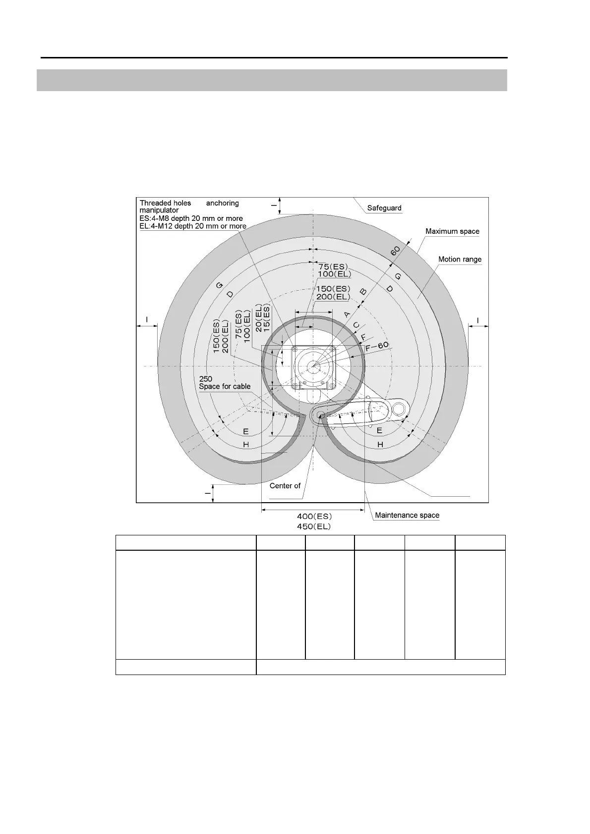
2.3 Base Table
A base table for anchoring the manipulator is not supplied. Users must make or obtain
such a table independently. The size and shape of the base table differs depending on the
robot’s application. For your reference, when designing or obtaining a base table, we have
listed some manipulator requirements.
If the controller will be mounted inside the table, please refer to the controller manual or
user’s guide, which describes space requirements and environmental conditions.
Area limited by
mechanical stop
for
Joint #3
Standard range of the manipulator
ES45** ES55** ES65** EL65** EL85**
A (arm #1 length)
B (arm #2 length)
C
D (motion range of the Joint #1)
E (motion range of the Joint #2)
F
G (
range to the stop of
J
oint #1
)
H (
range to the stop of
J
oint #2
)
215 mm
235 mm
156 mm
125 °
140 °
136 mm
130 °
145 °
315 mm
235 mm
203 mm
125 °
140 °
182 mm
130 °
145 °
415 mm
235 mm
280 mm
125 °
140 °
260 mm
130 °
145 °
300 mm
350 mm
228 mm
130 °
140 °
201 mm
132 °
145 °
500 mm
350 mm
324 mm
130 °
140 °
292 mm
132 °
145 °
I (range to the safeguard ) approx. 100 mm *
* In this case the safeguard completely prevents a person from touching the robot, such as a
transparent acrylic cover, for example. Refer to the Safety chapter in the “User’s Guide”
or “SRC5**/SPEL 95 Introduction manual” or “User’s manual” for the actual dimension
of “I”.
Figure 2. Manipulator installation dimensions [unit: mm]
 Loading...


