Part 1: Setup & Operation 5. End Effectors
19
5. End Effectors
5.1 Attaching an end effector
Users are responsible for making their own end effector(s). Here, we point out some
precautions to adhere to when attaching an end effector.
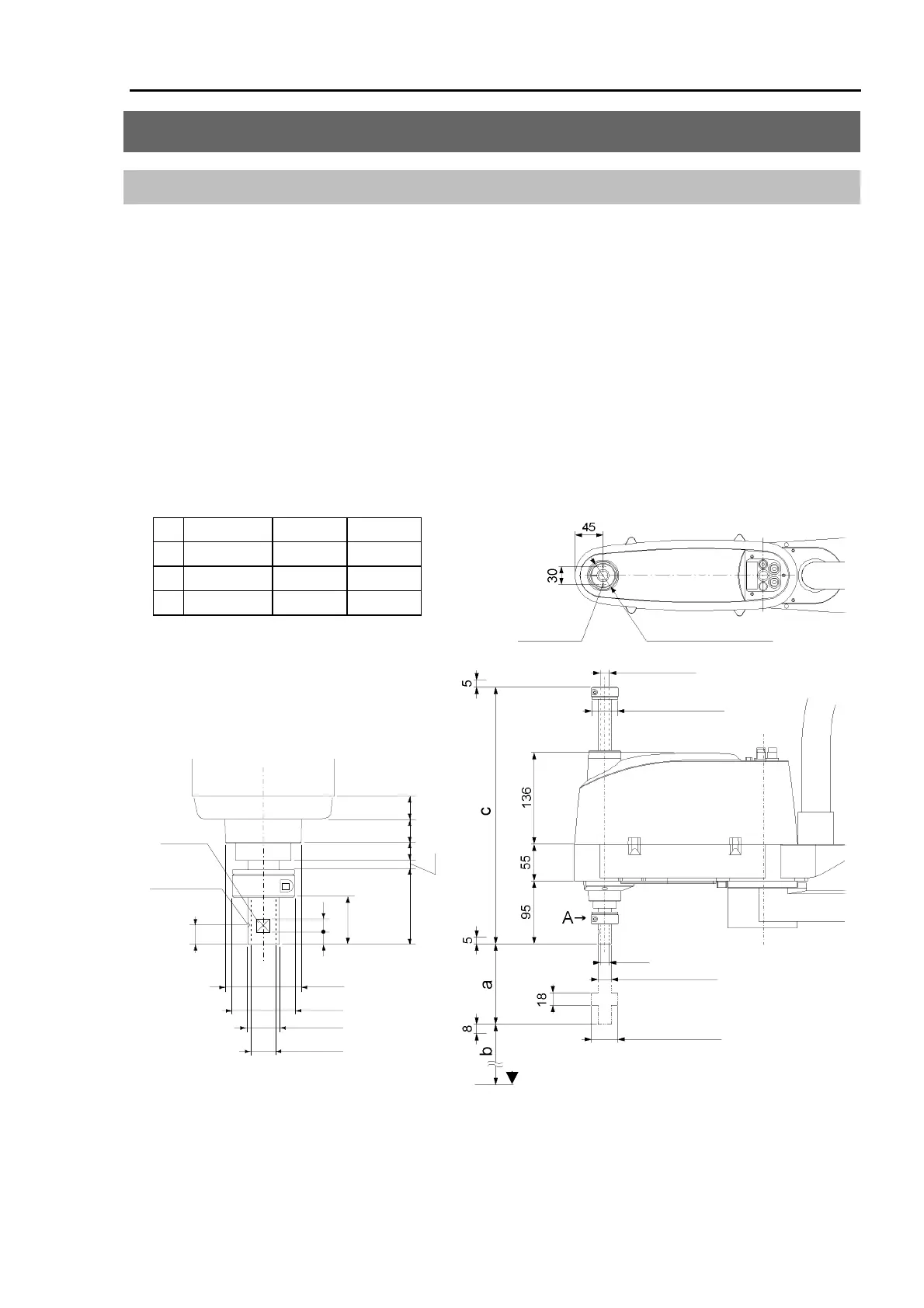
Install an end effector to the lower end of the shaft. Figure 10 shows the dimensions around
the shaft. See to Figure 20 in 7. External Dimensions for overall dimensions.
When you operate the manipulator with an end effector attached, the end effector could touch
the main body of the manipulator depending on the outer diameter of the end effector, the size
of the work piece or the position of the arms. When you are laying out the system, pay close
attention to the interference area of the end effector.
* If the manipulator is a Clean model, refer to chapter 11. Clean Model.
* If the manipulator is a Protected model, refer to chapter 12. Protected Model.
ES**1S ES**3S EL**3S
a
170 320 320
b
119
-31
-10
c
385 535 535
The shaft of E***3S will reach lower than
the bottom of the manipulator base when it
is fully lowered. Pay attention to it when
you design a layout
.
15
15
15
15
5
10
48
30
10
1 mm
Conical hole
Flat cut
φ
4, 90
°
φ
20h7
φ
14 through-hole
φ
39.5
φ
40
View A detail
(Calibration point position of Joint #3 & #4)
stop diameter
Lower-limit mechanical
φ
39.5
φ
14 Through
hole diameter
2-M4 Depth 10
The bottom of the
manipulator base
φ
20h7 shaft diameter
φ
14
φ
44 Bellows diameter
stop diameter
Upper-limit mechanical
φ
39.5
*
*
*
(
*
) indicates the stroke margin by the mechanical stop.
Figure 10. Dimensions around the shaft of Standard model [Unit :mm]
 Loading...


