Part 2: Maintenance 6. Replacing the Reduction Gear Units
139
6.2 Replacing the Joint #2 Reduction Gear Unit
* For protected models, contact the suppliers since the following procedure will not
apply.
Removal : Joint #2
(1) Open the arm top cover. (Refer to chapter 2. Opening the Covers.)
(2) Remove the duct plate from Arm #2 by unscrewing the three bolts (M4×8).
M4×8
Duct plate
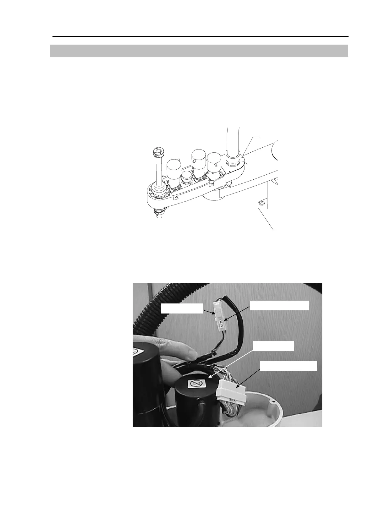
(3) Cut off the wire ties which fasten the Joint #2 motor and cables.
(4) Disconnect the signal connector X21 and power connector X121 of the Joint #2 motor.
To disconnect X121, pull it out while pushing the presser tongue next to the connector
number on the motor side.
Joint #2 motor
Signal connector X21
Power connector X121
Presser tongue
(5) Support Arm #2 with more than one person. While the arm is being supported, have
another person unscrew the four fastening bolts (M6×18 for the ES series; M8×18 for
the EL series) and remove Arm #2 from Arm #1.