Part 2: Maintenance 13. Protected Model Maintenance
211
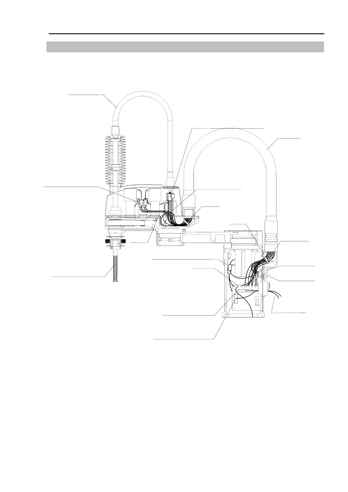
13.5 Wiring Schematic 1
To remove the cable unit, remove the connectors in the arm top cover and base. These
connectors are connected as shown in the figure below. For more information, see the
block diagram on the next page and the wiring list in 4. Connector Pin Assignments.
User cable duct
Receptacle
Ground×8
Ground
Fittings for φ6
pneumatic tube (×2)
Fitting for φ4
pneumatic tube (×1)
Wire tie
Cable unit
Wire tie
φ
4 pneumatic tube (
×
3)
User cable (
×
15)
Signal connector X1
(connects with following
connectors on the other side:
Joint #1 X10
Joint #2 X20
Joint #3 X30
Joint #4 X40)
Joint #1 Power connector X110
Joint #1 Signal connector X11
Signal cable
User cable
Fittings for φ4/6 pneumatic tube (×2)
Fitting for φ4 pneumatic tube (×1)
User connector X51, X52
Connectors
Joint #3 Power X131
Joint #3 Signal X31
Joint #3 Brake X32
Joint #3 Brake
release button X33
Joint #4 Power X141
Joint #4 Signal X41
Connectors
Joint #2 Power X121
Joint #2 Signal X21
User connector (connects
with X50 on the other side)
 Loading...


