Part 1: Setup & Operation 8. Motion Range and Robot Coordinates
47
(1) Exit EPSON RC+, shut down the SPEL Runtime Drivers, and turn OFF the Drive
Unit.
(1) Exit SPEL 95, and turn OFF the Drive Unit.
(1) Turn OFF the controller.
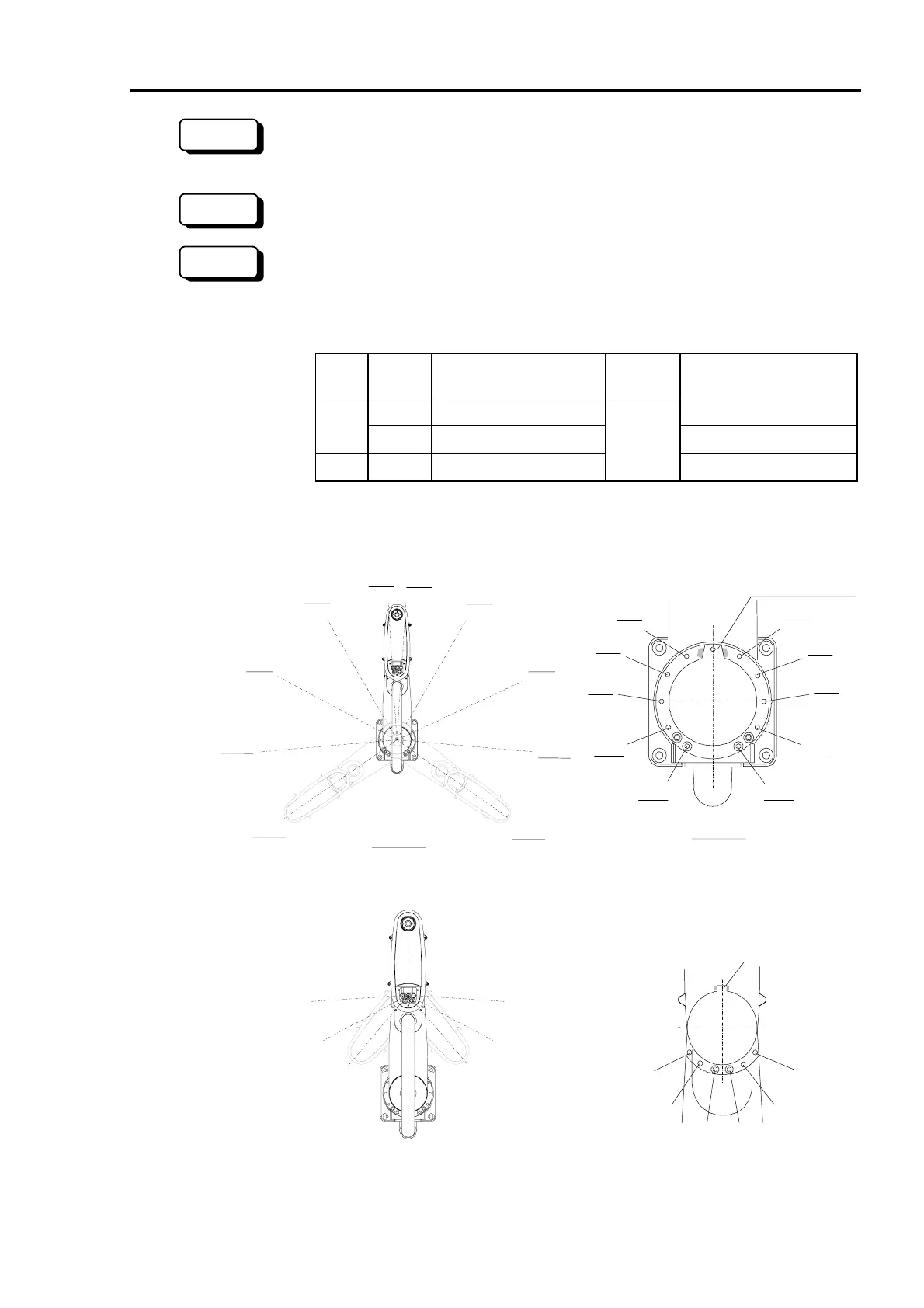
(2) Screw a hexagon socket head cap bolt into each of the holes corresponding to the
angle setting.
Joint Series
Hexagon socket head cap
bolt (fully threaded)
Number
of bolts
Recommended tightening
torque
ES M8×10 3720N⋅cm (380kgf⋅cm)
#1
EL M12×20 12740N⋅cm (1300kgf⋅cm)
#2 ES/EL M8×10
1/side
3720N⋅cm (380kgf⋅cm)
Threaded hole locations corresponding to the angle setting are shown below.
Joint #1
EL series
ES series
+35
°
+40
°
+65
°
+70
°
+95
°
+100
°
+125
°
+130
°
-
35
°
-
40
°
-
65
°
-
70
°
-
95
°
-
100
°
+125
°
+130
°
+5
°
+10
°
-
5
°
-
10
°
EL series
ES series
Mechanical stop for
joint #1
+5
+10
-
5
-
10
+35
+40
-
35
-
40
+65
+70
-
65
-
70
+95
+100
-
95
-
100
+125
+130
-
125
-
130
Joint #2
-
95
°
+95
°
-
120
°
-
140
°
+140
°
+120
°
Mechanical stop for
joint #2
-
95 +95
-
120
-
140 +140
+120
Figure 29. Threaded holes for changing the position of mechanical stops
300
RC+
SPEL 95
 Loading...


