8. Motion Range and Robot Coordinates Part 1: Setup & Operation
48
(3) Turn ON the Drive Unit, and start EPSON RC+.
(3) Turn ON the Drive Unit, and start SPEL 95.
(3) Turn ON the controller.
(4) Set the pulse range corresponding to the new positions of the mechanical stops using
the RANGE tab in the Project | Robot Parameters dialog. (Refer to the chapter
EPSON RC+ GUI in the EPSON RC+ User’s Guide.) You may also execute the
RANGE or JRANGE from the EPSON RC+ Monitor Window.
(4) Set the pulse range corresponding to the new positions of the mechanical stops using
the [RANGE] panel. (Refer to Setting the Robot Parameters in chapter 11 of the
User’s Guide.
(4) Set the pulse range corresponding to the new positions of the mechanical stops using
either the RANGE or JRANGE command.
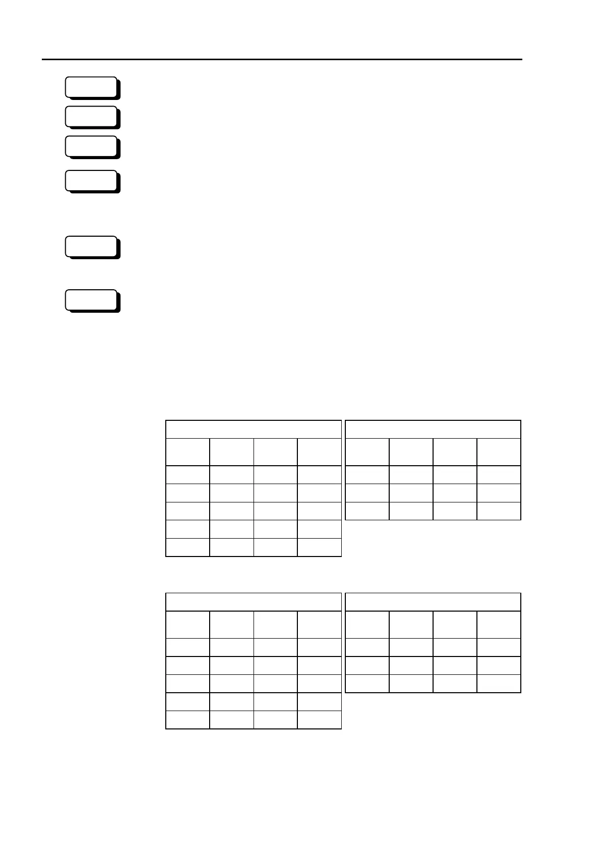
The pulse value corresponding to the angle setting in Figure 29 is described in the
tables below.
Always set the pulse range to the inside of the position of the mechanical stops.
ES series Angle setting and Pulse value
Joint #1 Joint #2
angle
setting
pulse
value
angle
setting
pulse
value
angle
setting
pulse
value
angle
setting
pulse
value
+5° 86472
-5°
77369 +95° 54045
-95° -54045
+35° 113778
-35°
50063 +120° 68267
-120° -68267
+65° 141085
-65°
22756 +140° 79645
-140° -79645
+95° 168392
-95° -4552
+125° 195698
-125° -31858
EL series Angle setting and Pulse value
Joint #1 Joint #2
angle
setting
pulse
value
angle
setting
pulse
value
angle
setting
pulse
value
angle
setting
pulse
value
+10° 113778
-10°
91022 +95° 86472
-95° -86472
+40° 147912
-40°
56888 +120° 109227
-120° -109227
+70° 182045
-70°
22755 +140° 127432
-140° -127432
+100° 216178
-100° -11378
+130° 250312
-130° -45512
NOTE
RC+
SPEL 95
300
300
RC+
SPEL 95
 Loading...


