EPSON WF-C5790/WF-C5790a/WF-C5710/ET-8700/WF-C5210/WF-C5290/WF-C5290a Revision A
Configuration and operating principles Operating principles 43
Confidential
3.3.1.2 Head Angular Mecha Adjustment
This section explains the head angular mecha adjustment for adjusting the inclination
of the Printhead on the CR Unit physically.
Overview
The nozzle arrangement of the μTFP4 head mounted on this printer differs from that
of the traditional printers. The nozzles of the same color are not arranged next to
each other. Therefore, the influence of the posture (inclination) of the Printhead of
this printer on the print quality is greater than that of the traditional printers' Print-
heads.
The inclination of the Printhead of the traditional printers is corrected with software
(the adjustment program).
1
However, the inclination of the Printhead of this printer
is corrected mechanically by adjusting the head angular adjustment dial mounted on
the carriage mechanism based on the result of visual check of the adjustment pattern
printed with the adjustment program.
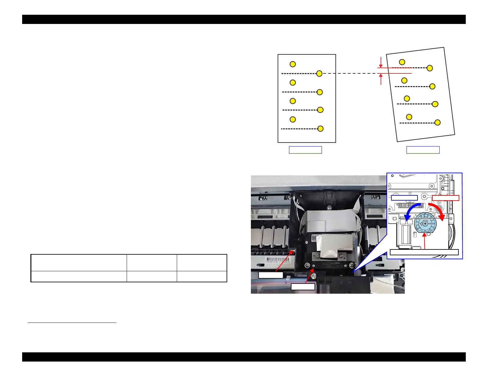
In this adjustment, the inclination of the Printhead is defined as the amount of mis-
alignment of the nozzles on row H and the center points of the spaces between the
nozzles on row A shown in Figure 3-21. The purpose of the adjustment is to elimi-
nate the misalignment (the inclination of the Printhead) completely.
Range of adjustment
By rotating the head angular adjustment dial, the Printhead is rotated on the pivot
point on the bottom. The relationship between the rotational direction of the Head
Angular Adjustment Dial and that of the Printhead is as follows.
The resolution performance of the Head Angular Adjustment Dial is approximately
12
m, and adjustable up to ± 144
m
Figure 3-21. Definition of the inclination of the Printhead
Figure 3-22. Head angular mecha adjustment
1. For the correction of the inclination of the Printhead of the traditional printers is made using software with the
calculation result of the amount of the inclination of the Printhead based on the result of visual check of the
adjustment pattern. For the band feeding used in the draft mode, the head angular adjustment using software;
different from the mechanical inclination correction explained here, is used.
Table 3-20. Rotational direction of Head Angular Adjustment Dial and that of Printhead
Rotational direction of Head Angular
Adjustment Dial
+ direction - direction
Rotational direction of Printhead CCW CW
Misalignment of
the nozzle
locations
Row A Row H
No inclination Inclined
Row A Row H
+ direction
- direction
Head Angular Adjustment Dial