EPSON WF-C5790/WF-C5790a/WF-C5710/ET-8700/WF-C5210/WF-C5290/WF-C5290a Revision A
Configuration and operating principles Operating principles 58
Confidential
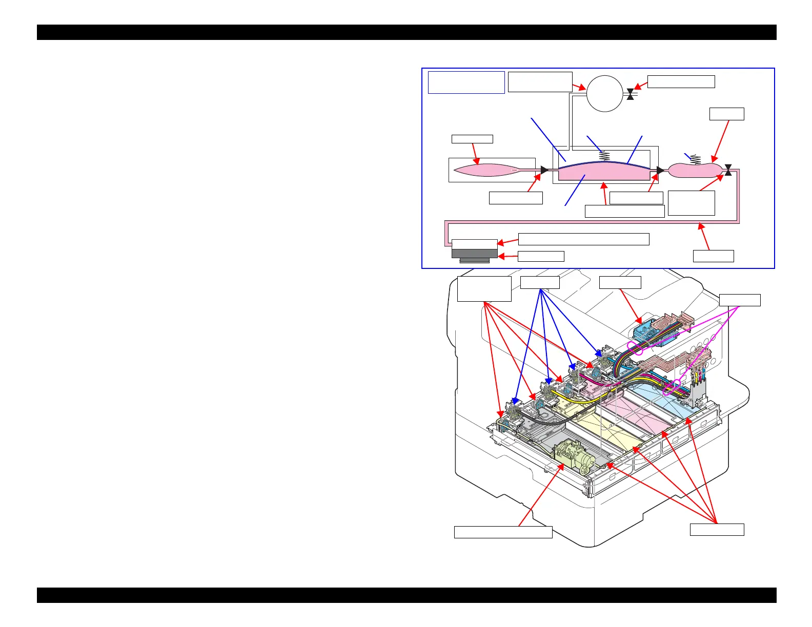
3.3.4 Ink Supply Mechanism
3.3.4.1 Overview
The ink supply mechanism consists of the Ink Supply Unit that is composed of
the Ink Supply Tube, Diaphragm Pump ,Buffer, and Decompression Motor,
and ink is supplied from the ink pack installed in the lower part of the product.
According to the quantity of ink discharged from the Print Head, ink is sucked
from the ink packs by the Decompress Pump Unit, Diaphragm Pump and
Buffer.
The ink path from the Buffer through the ink tube to the selfsealing valve in the
Printhead is always kept pressurized even after the power is turned off by the
check valves and the Diaphragm Pump. Therefore, ink can be supplied stably
during high-volume printing.
3.3.4.2 Operating principles
Ink supply becomes ready by installing the ink pack into the Ink Pack Unit in
the lower part of the product.
The Ink Pack Unit also mounts the CR Contact Module to detect the remaining
ink amount in the ink pack.
The diaphragm is operated when the Decompress Pump Unit reduces the
pressure inside the Diaphragm Pump, and it sucks ink from the ink packs Ink is
supplied through the Buffer and ink tube to the Print Head.
The Decompress Pumps and Diaphragm Pumps supply sufficient ink needed
for the quantity of the Prinhead's ink discharge in high speed printing with high
image quality.
Figure 3-37. Ink supply mechanism
Ink Pack
Self-sealing Valve (in Printhead)
Printhead
Decompression
Motor
Diaphragm Pump
Buffer
Check Valve
Film Choke
Valve
Ink Chamber
Air chamber
Ink path simplified
model
Diaphragm (rubber film)
Spring
Spring
Ventilation Valve
Check Valve
Ink Tube
Printhead
Decompression Motor
Ink Pack
Diaphragm
Pump
Buffer
Ink Tube