80 UMFLUXUS_G6V4-2EN, 2011-03-29
FLUXUS G60x 11 Basic Measurement
11 Basic Measurement
11.6.1 Fine Adjustment of the Transducer Distance
In case of large deviations, check if the entered parameters are correct or repeat the
measurement at a different point on the pipe.
Repeat the steps for all channels on which will be measured. The measurement will be
started automatically afterwards.
If the displayed transducer distance is adjusted, press EN-
TER.
The measuring for the positioning of the transducers is
started.
The amplitude of the received signal is displayed by the
bar graph S=.
If the LED of the measuring channel lights green, the sig-
nal is sufficient for a measurement.
If the LED of the measuring channel lights red, the signal is
not sufficient for a measurement.
• Shift a transducer slightly in the range of the recom-
mended transducer distance until the LED of the mea-
suring channel lights green.
The following can be displayed in the upper line with key
and in the lower line with key :
• transducer distance
• C (SNR - signal-to-noise ratio)
If min. one box is displayed, the signal is sufficient for
the measurement. Three or more boxes are optimal for a
measurement.
• bar graph Q= (signal quality), must have max. length
• transit time time in µs
• bar graph S= (signal amplitude)
If the signal is not sufficient for measurement, Q= UNDEF
will be displayed.
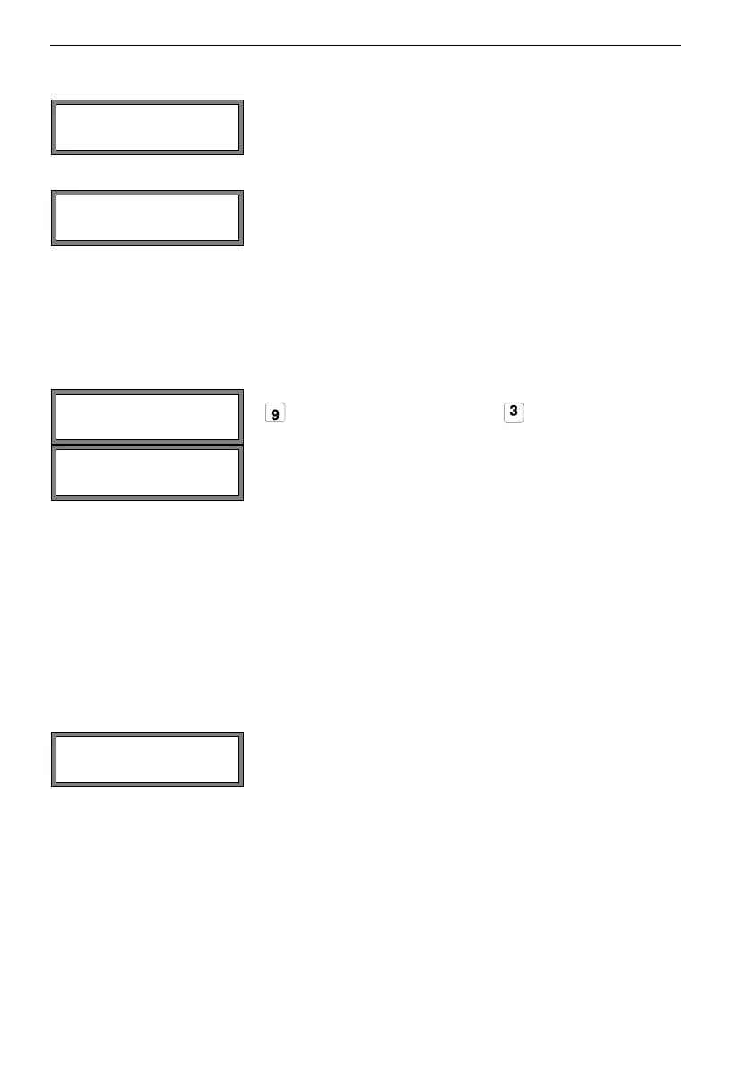
After the precise positioning of the transducers, the recom-
mended transducer distance is displayed again.
Enter the actual (precise) transducer distance. Press EN-
TER.
Transd. Distance
A: 54 mm !
time= 94.0 s
Q=
Transd. Distance?
53.9 mm