6 Installation of FLUXUS G601 FLUXUS G60x
UMFLUXUS_G6V4-2EN, 2011-03-29 35
6.4.2 Operation with the Power Supply Unit
• Connect the power supply unit to the socket on the upper side of the transmitter (see
Fig. 6.7).
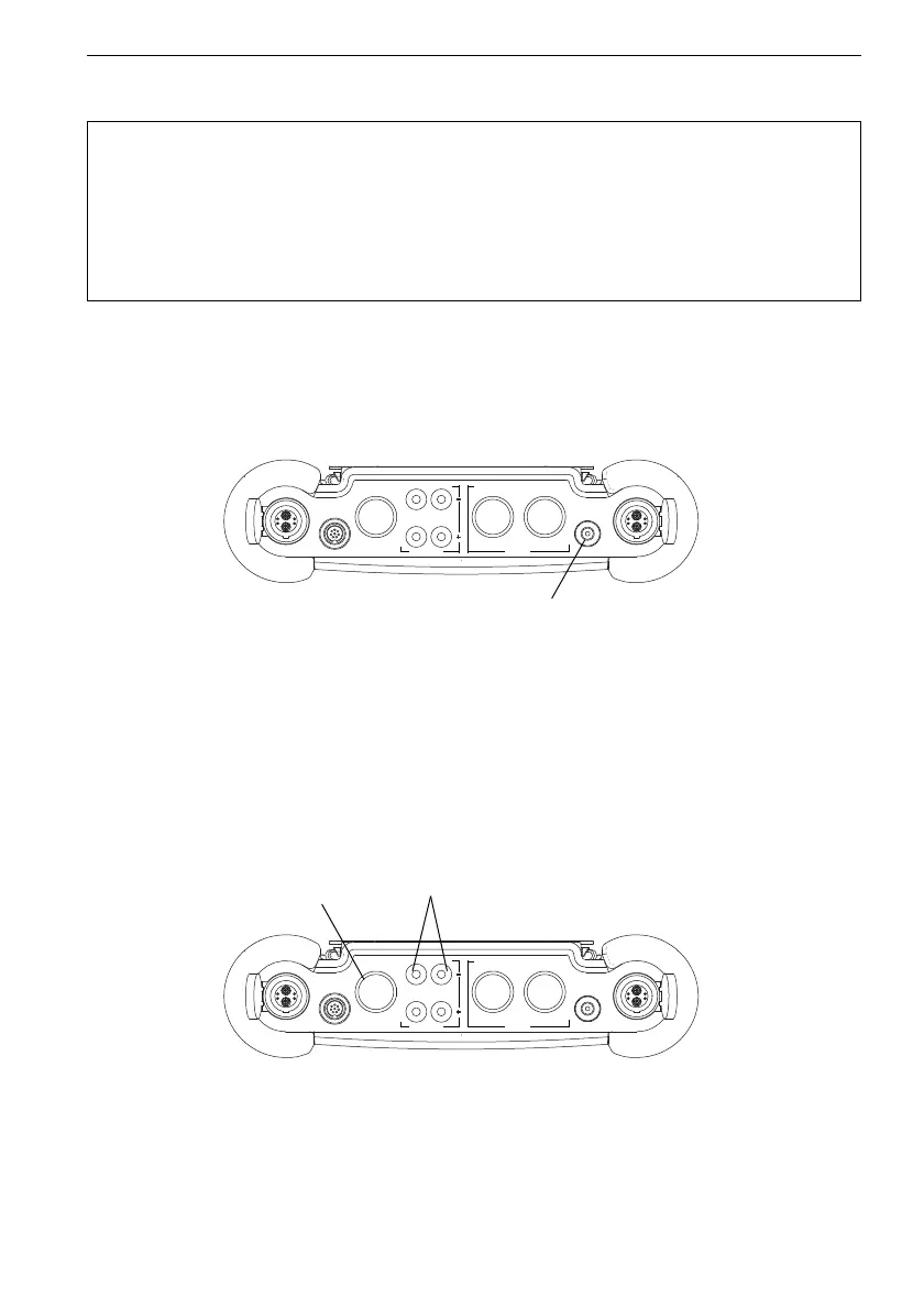
6.5 Connection of the Outputs
For the connection of the outputs, see Fig. 6.8 and Tab. 6.1.
Attention! • Use only the supplied power supply unit.
• The power supply is not protected against moisture. Use it only in
dry rooms.
• The voltage indicated on the power supply unit must not be ex-
ceeded.
• Do not connect a defective power supply unit to the transmitter.
Fig. 6.7: Connections of the transmitter FLUXUS G601
Fig. 6.8: Connections of the transmitter FLUXUS G601
CH A
COMM
P2 P1
Output Input
CH B
T1/T3 T2/T4
DC-IN
P3...P8
power supply unit/
battery charging unit
CH A
COMM
P2 P1
Output Input
CH B
T1/T3 T2/T4
DC-IN
P3...P8
outputs
output
adapter