44 UMFLUXUS_G6V4-2EN, 2011-03-29
FLUXUS G60x 7 Installation of FLUXUS G608
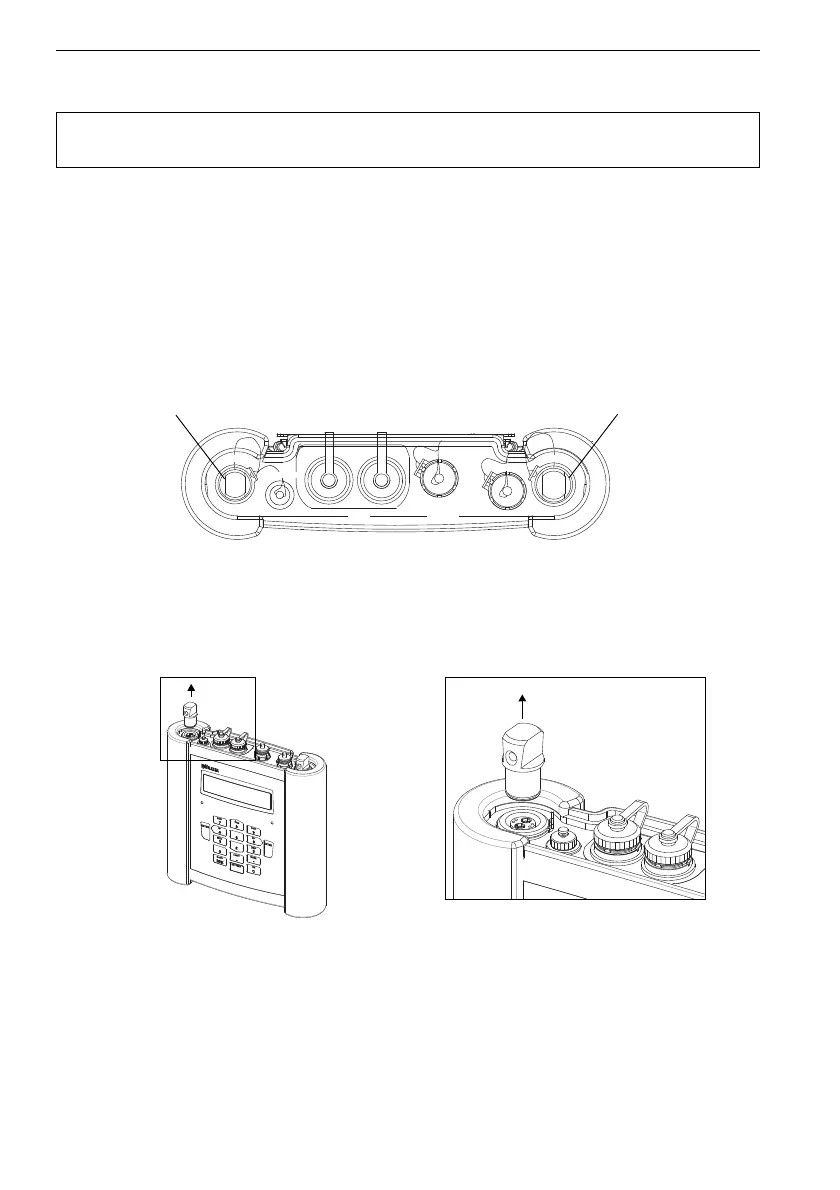
7.3 Connection of the Transducers
The connections are on the upper side of the transmitter (see Fig. 7.5).
• Remove the blind plug (see Fig. 7.6).
• Insert the connector of the transducer cable in the socket of the transmitter. The red
point (a) on the connector must align with the red marking (b) on the socket (see Fig.
7.7).
Attention! Observe the Safety Instructions for the Use in Explosive Atmo-
sphere (see document SIFLUXUS_608).
Fig. 7.5: Connections of the transmitter FLUXUS G608
Fig. 7.6: Removing the blind plug
transducers
measuring channel A
transducers
measuring channel B
CH A
COMM
OutputInput
DC-IN
CH B