32 UMFLUXUS_G6V4-2EN, 2011-03-29
FLUXUS G60x 6 Installation of FLUXUS G601
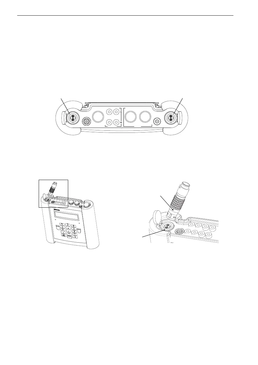
6.3 Connection of the Transducers
The connections are on the upper side of the transmitter (see Fig. 6.5).
• Pull up the socket cover (see Fig. 6.6).
• Insert the connector of the transducer cable in the socket of the transmitter. The red
point (a) on the connector must align with the red marking (b) on the socket.
Fig. 6.5: Connections of the transmitter FLUXUS G601
Fig. 6.6: Connection of the transducers
transducers
measuring channel B
transducers
measuring channel A
CH A
COMM
P2 P1
Output Input
CH B
T1/T3 T2/T4
DC-IN
P3...P8