7 Installation of FLUXUS G608 FLUXUS G60x
UMFLUXUS_G6V4-2EN, 2011-03-29 51
7.6 Connection of the Inputs (Optional)
7.6.1 Connection of a Temperature Input
Temperature probes Pt100/Pt1000 (4-wire) can be connected to the inputs of the trans-
mitter (optional) (see Fig. 7.11).
For the assignment and the activation of the temperature inputs see chapter 20.
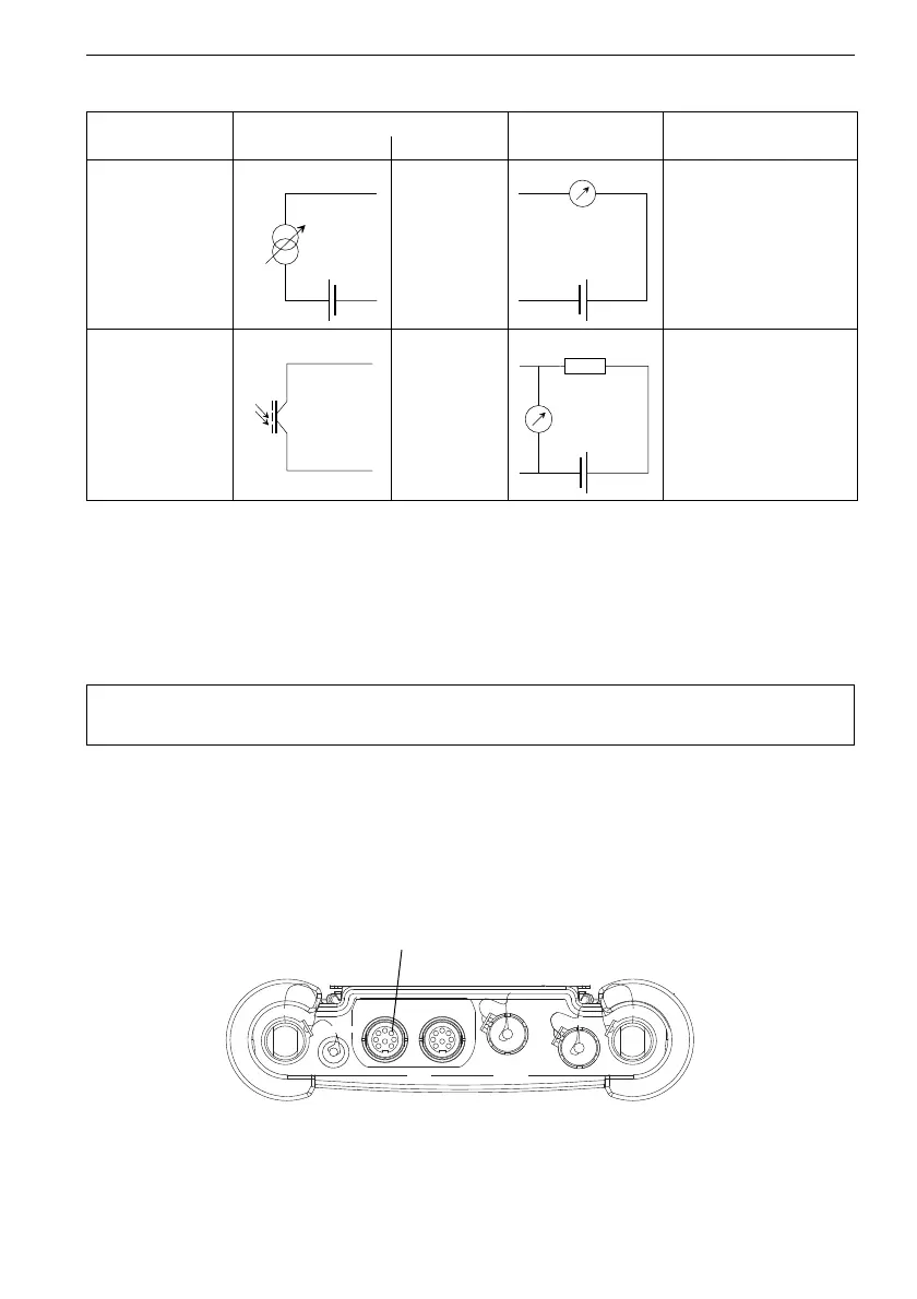
Tab. 7.2: Circuits of the outputs
output transmitter external circuit remark
internal circuit connection
passive current
loop (semi-pas-
sive design)
Px+
Px-
U
ext
=
4...9 V
U
ext
> 0.021 A
.
R
ext
[Ω]
+ 4 V
example:
U
ext
= 6 V
R
ext
= 0...90 Ω
binary output (op-
torelay)
Px+
Px-
Uext
≤
26
V
I
c
≤ 100 mA
The number, type and connections of the outputs are customized.
R
ext
is the sum of all ohmic resistances in the circuit (e.g. resistance of the conductors, resistance of
the amperemeter/volt-meter).
Attention! Observe the Safety Instructions for the Use in Explosive Atmo-
sphere (see document SIFLUXUS_608).
Fig. 7.11: Connection of the transmitter FLUXUS G608
inputs
CH A
COMM
OutputInput
DC-IN
CH B