36 UMFLUXUS_G6V4-2EN, 2011-03-29
FLUXUS G60x 6 Installation of FLUXUS G601
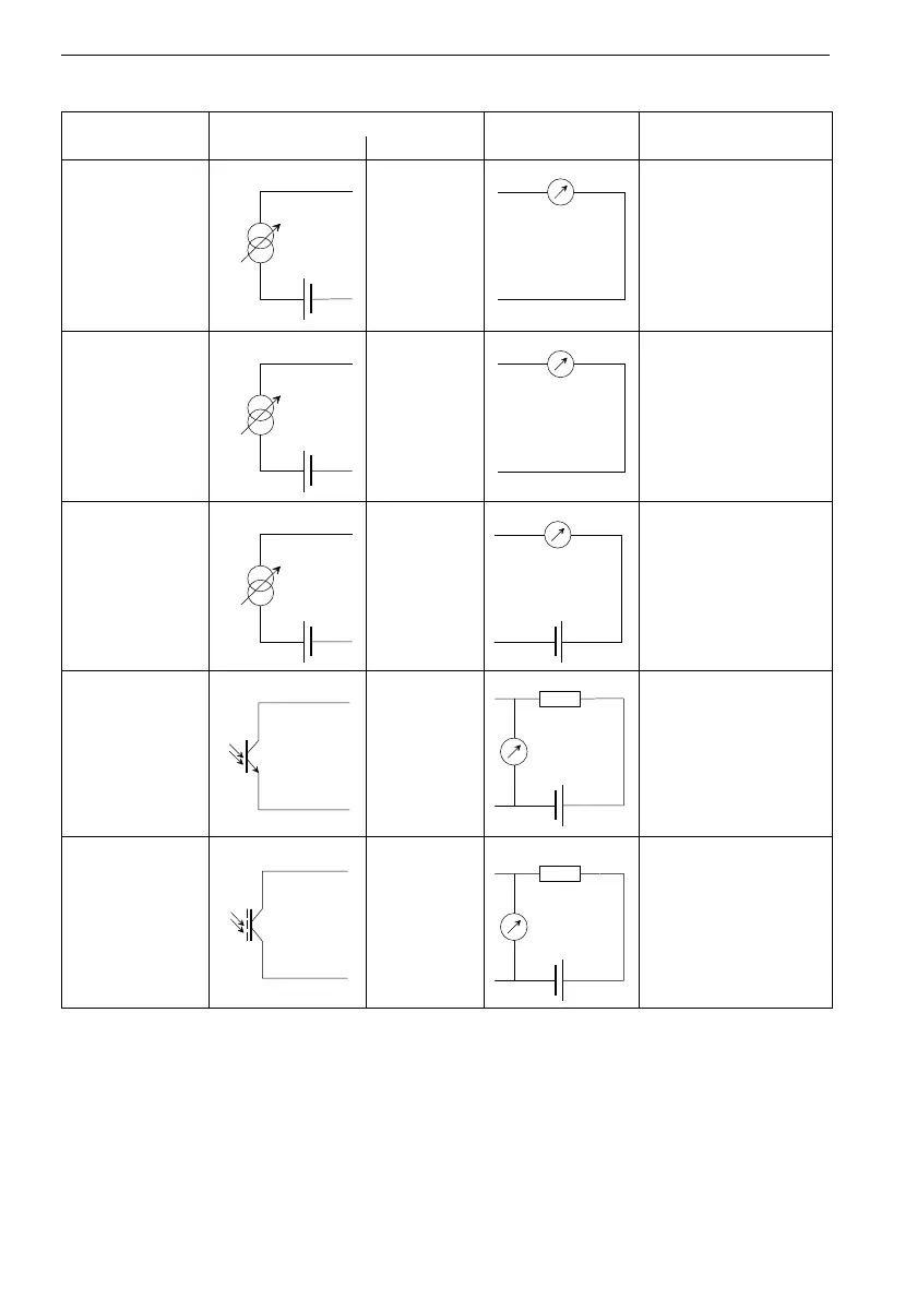
Tab. 6.1: Circuits of the outputs
output transmitter external circuit remark
internal circuit connection
active current
loop
Px+
Px-
R
ext
< 200 Ω
passive current
loop
(semi-passive
design, used as
active current
loop)
Px+
Px-
R
ext
< 50 Ω
e.g. for local connection
of a multimeter
passive current
loop (semi-pas-
sive design)
Px+
Px-
U
ext
=
4...16 V
U
ext
> 0.021 A
.
R
ext
[Ω]
+ 4 V
example:
U
ext
= 12 V
R
ext
= 0...380 Ω
frequency output
Px+
Px-
U
ext
= 5...24 V
R
c
[kΩ] = U
ext
/I
c
[mA]
I
c
= 1...4 mA
binary output (op-
torelay)
Px+
Px-
Uext
≤
26
V
I
c
≤ 100 mA
The number, type and connections of the outputs are customized.
R
ext
is the sum of all ohmic resistances in the circuit (e.g. resistance of the conductors, resistance of
the amperemeter/volt-meter).