STP Configuration
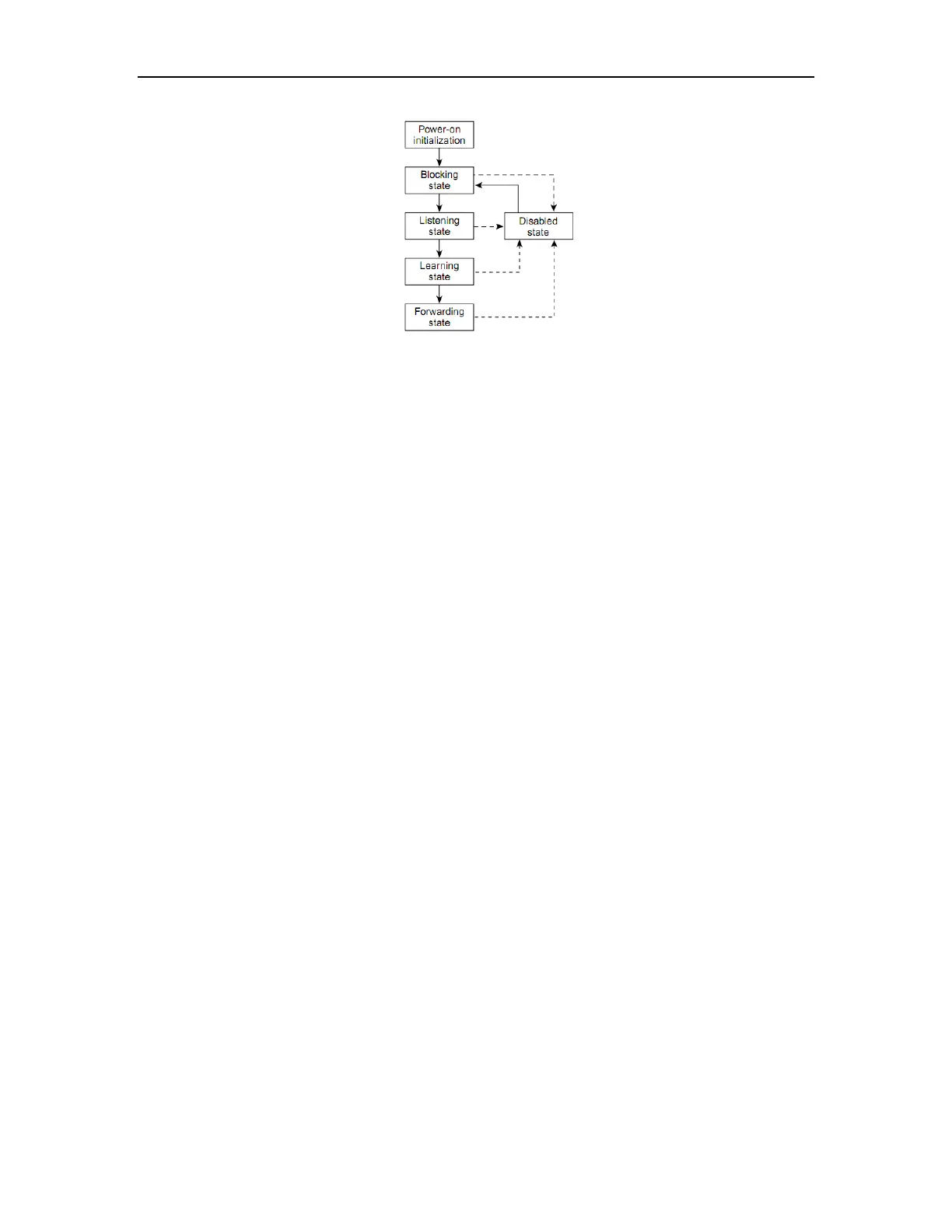
Figure 21-1 Spanning-Tree Interface States
When you power up the switch, spanning tree is enabled by default, and every interface in
the switch, VLAN, or network goes through the blocking state and the transitory states of
listening and learning. Spanning tree stabilizes each interface at the forwarding or blocking
state.
When the spanning-tree algorithm places a Layer 2 interface in the forwarding state, this
process occurs:
1. The interface is in the listening state while spanning tree waits for protocol information to
transition the interface to the blocking state.
2. While spanning tree waits the forward-delay timer to expire, it moves the interface to the
learning state and resets the forward-delay timer.
3. In the learning state, the interface continues to block frame forwarding as the switch
learns end-station location information for the forwarding database.
4. When the forward-delay timer expires, spanning tree moves the interface to the
forwarding state, where both learning and frame forwarding are enabled.
21.2 How STP Works
STP identifies the network topology by transmitting configuration BPDUs between network
devices. Configuration BPDUs contain sufficient information for network devices to complete
the spanning tree calculation. Important fields in a configuration BPDU include:
Root bridge ID: consisting of root bridge priority and MAC address.
Root path cost: the cost of the shortest path to the root bridge.
Designated bridge ID: designated bridge priority plus MAC address.
Designated port ID, designated port priority plus port name.
Message age: age of the configuration BPDU while it propagates in the network.
Max age: maximum age of the configuration BPDU maintained in the device.
Hello time: configuration BPDU interval.
 Loading...