Configuring MSTP
point to point link type, used to quickly convert the port state to Forwarding state.
23.3.7 MST and SST Compatibility
MSTP protocol and the MSTP-enabled switch does not support the MSTP switch is divided
into different regions, respectively, called the MST region and SST fields, the Ministry of the
MST region to run multiple instances of spanning tree, the edge in an MST region to run
RSTP compatible protocol.
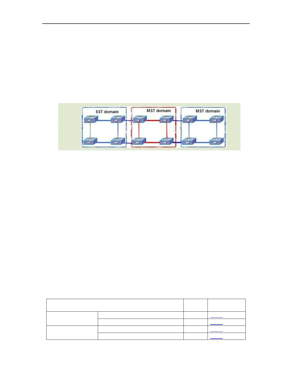
Diagram below shows MSTP works:
Figure 23-12
The middle of the red MST region use MSTP BPDU exchange between the switch
topology information, the blue region of the switch use the SST STP / RSTP BPDU exchange
topology information.
MST region and SST fields between the edge of the port on the MSTP processing is
slightly more complicated:
When the edge of the other switch port receives STP BPDU sent by the time the port will
enter the STP-compliant state, sending STP BPDU;
When the edge of the port when the received RSTP BPDU, the port will enter the
RSTP-compatible state, but still send MSTP BPDU. Because RSTP to consider when
designing the expansion, so the equipment side of the RSTP MSTP packets can be
understood as the right RSTP packets.
23.4 Configuring MSTP
23.4.1 Configuring MSTP Task
Table 23-1 Configuring MSTP task
Adjust and optimize
the MSTP
Configure bridge forward delay
Configure bridge hello time
 Loading...