Basic System Configuration & Debugging
Display SNMP user information
Display the currently
configured view
28.2.4 SNMP Configuration Example
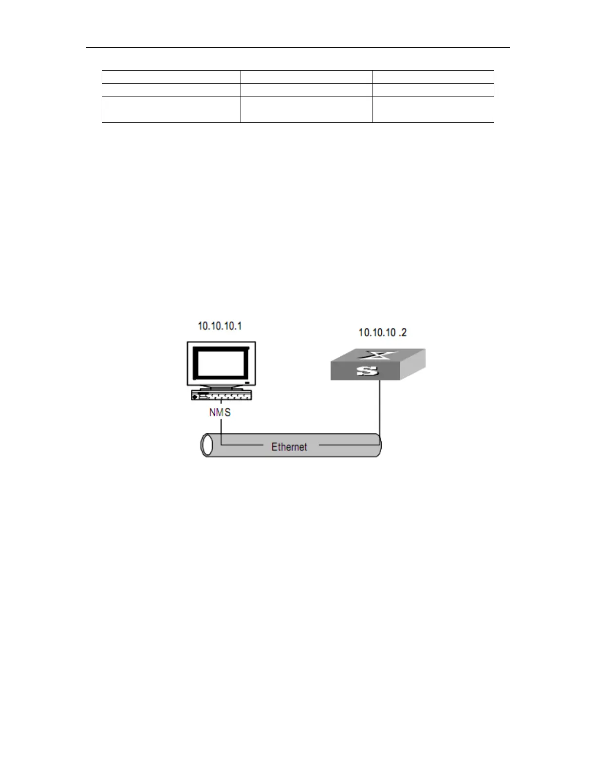
28.2.4.1 Network requirements
An NMS and Switch A are connected through the Ethernet. The IP address of the NMS is
10.10.10.1 and that of the VLAN interface on Switch A is 10.10.10.2.
Perform the following configuration on Switch A: setting the community name and access
authority, administrator ID, contact and switch location, and enabling the switch to sent trap
packet.
28.2.4.2 Network diagram
FIgure 28-2 Network diagram for SNMP
28.2.4.3 Network procedure
! Set the community name, group name and user.
Switch(config)# snmp-server community FoxGate ro permit
Switch(config)# snmp-server group grp1 1 read internet write internet notify Internet
Switch(config)# snmp-server user user1 grp1
! Enable the SNMP agent to send Trap packets to the NMS whose IP address is
10.10.10.1. The SNMP community is FoxGate.
Switch(config)#snmp-server host 1.1.1.2 version 3 auth 1 notify-type interfaces
 Loading...