VLAN Configuration
specific hosts. When the physical position of a host changes within the range of the VLAN,
you need not change its network configuration.
9.2 VLAN Principles
VLAN tags in the packets are necessary for the switch to identify packets of different
VLANs. The switch works at Layer 2 (Layer 3 switches are not discussed in this chapter) and
it can identify the data link layer encapsulation of the packet only, so you can add the VLAN
tag field into only the data link layer encapsulation if necessary.
In 1999, IEEE issues the IEEE 802.1Q protocol to standardize VLAN implementation,
defining the structure of VLAN-tagged packets.
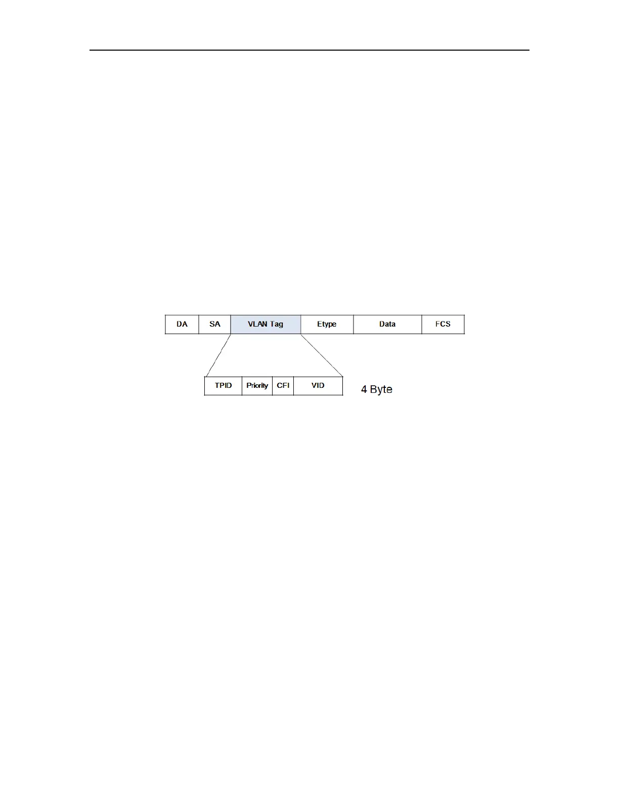
IEEE 802.1Q protocol defines that a 4-byte VLAN tag is encapsulated after the destination
MAC address and source MAC address to show the information about VLAN.
Figure 9-2 Format of VLAN tag
As shown in Figure 9-2, a VLAN tag contains four fields, including TPID (Tag Protocol
Identifier), priority, CFI (Canonical Format Indicator), and VID (VLAN ID).
TPID is a 16-bit field, indicating that this data frame is VLAN-tagged. By default, it is
0x8100.
Priority is a 3-bit field, referring to 802.1p priority. Refer to section “QoS & QoS profile” for
details.
CFI is a 1-bit field, indicating whether the MAC address is encapsulated in the standard
format in different transmission media. This field is not described in detail in this chapter.
VID (VLAN ID) is a 12-bit field, indicating the ID of the VLAN to which this packet belongs.
It is in the range of 0 to 4,095. Generally, 0 and 4,095 is not used, so the field is in the range of
1 to 4,094.
VLAN ID identifies the VLAN to which a packet belongs. When the switch receives an
un-VLAN-tagged packet, it will encapsulate a VLAN tag with the default VLAN ID of the
inbound port for the packet, and the packet will be assigned to the default VLAN of the
inbound port for transmission. For the details about setting the default VLAN of a port, refer to
section “02-Port Configuration”
 Loading...