STP Configuration
By comparison:
Because the root path cost of CP2 (9) (root path cost of the BPDU
(5) plus path cost corresponding to CP2 (4)) is smaller than the
root path cost of CP1 (10) (root path cost of the BPDU (0) + path
cost corresponding to CP2 (10)), the BPDU of CP2 is elected as
the optimum BPDU, and CP2 is elected as the root port, the
messages of which will not be changed.
After comparison between the configuration BPDU of CP1 and the
calculated designated port configuration BPDU, port CP1 is
blocked, with the configuration BPDU of the port remaining
unchanged, and the port will not receive data from Device A until
a spanning tree calculation process is triggered by a new
condition, for example, the link from Device B to Device C
becomes down.
Blocked port CP2:
{0, 0, 0, AP2}
Root port CP2:
{0, 5, 1, BP2}
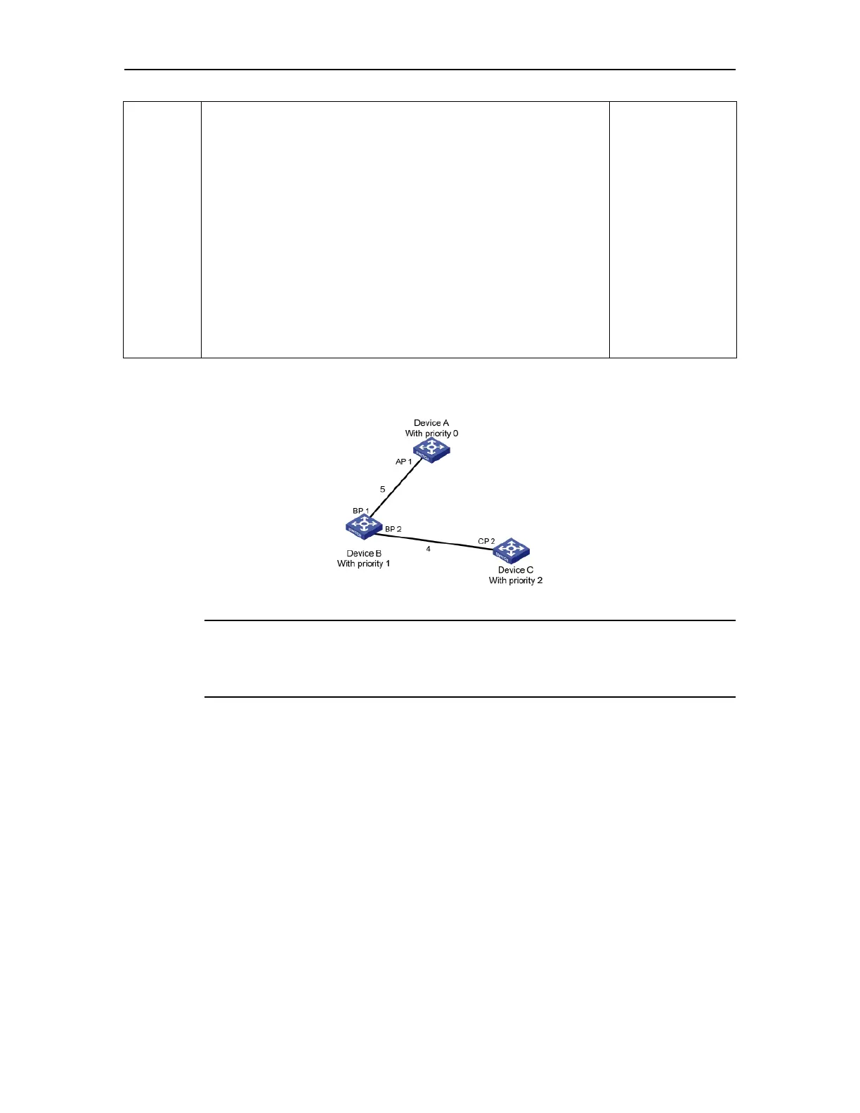
After the comparison processes described in the table above, a spanning tree with Device
A as the root bridge is stabilized, as shown in Figure 21-3.
Figure 21-3 The final calculated spanning tree
Note:
To facilitate description, the spanning tree calculation process in this example is
simplified, while the actual process is more complicated.
2) The BPDU forwarding mechanism in STP
Upon network initiation, every switch regards itself as the root bridge, generates
configuration BPDUs with itself as the root, and sends the configuration BPDUs at a
regular interval of hello time.
If it is the root port that received the configuration BPDU and the received
configuration BPDU is superior to the configuration BPDU of the port, the device will
increase message age carried in the configuration BPDU by a certain rule and start a
timer to time the configuration BPDU while it sends out this configuration BPDU
through the designated port.
If the configuration BPDU received on the designated port has a lower priority than
the configuration BPDU of the local port, the port will immediately send out its better
 Loading...