Flex Links Configuration
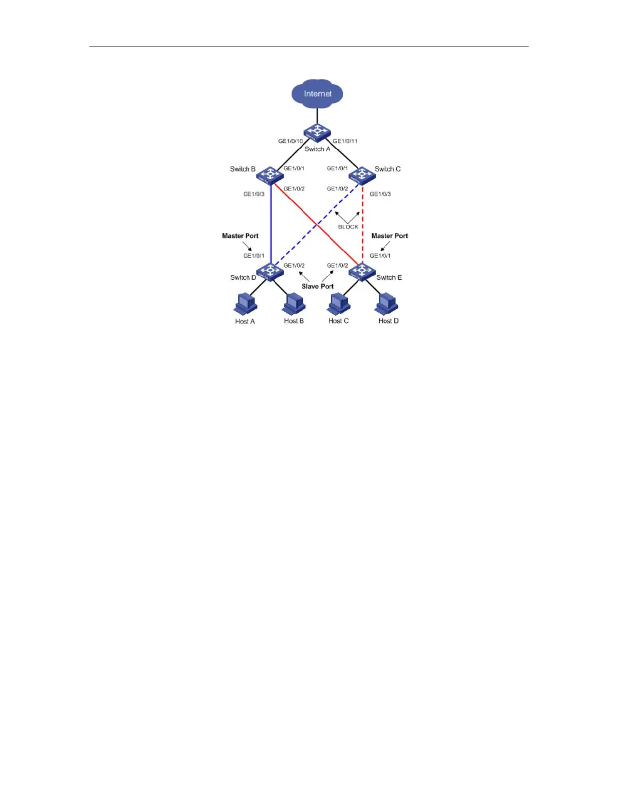
Figure 32-1 Flex Link application scenario
As shown in Figure 32-1, GigabitEthernet 1/0/1 and GigabitEthernet 1/0/2 of Switch D form
a Flex link group (marked in blue). GigabitEthernet 1/0/1 is in the forwarding state (marked by
a continuous line), and GigabitEthernet 1/0/2 is in the blocked state (marked by a broken line).
GigabitEthernet 1/0/1 and GigabitEthernet 1/0/2 of Switch E form another Flex link group
(marked in red). GigabitEthernet 1/0/1 is in the blocked state (marked by a broken line), and
GigabitEthernet 1/0/2 is in the forwarding state (marked by a continuous line).
Master port
The master port of a Flex link group is a port role specified using commands. It can be an
Ethernet port (electrical or optical), or an aggregate interface.
As shown in Figure 32-1, the active port in the Flex link group configured on Switch D is
the master port GigabitEthernet 1/0/1, while that in the Flex link group on Switch E is the slave
port GigabitEthernet 1/0/2. Although GigabitEthernet 1/0/1 of Switch E is blocked, it is still the
master port.
Slave port
The slave port of a Flex link group is another port role specified using commands. It can be
an Ethernet port (electrical or optical), or an aggregate interface. The link on which the slave
port resides is called the backup link.
As shown in Figure 32-1, the blocked port in the Flex link group on Switch D is the slave
port GigabitEthernet 1/0/2, while that in the Flex link group on Switch E is the master port
 Loading...