Monitor Link Configuration
using commands. It can be an Ethernet port (electrical or optical), or an aggregate interface.
As shown in Figure 33-2, GigabitEthernet 1/0/2 and GigabitEthernet 1/0/3 of Switch A are
two downlink ports of the monitor link group configured on the device.
Note:
When a monitor link group’s uplink ports recover, only downlink ports that were
blocked due to uplink port failure will be brought up. Downlink ports manually shut
down will not be brought up automatically. The failure of a downlink port does not
affect the uplink ports or other downlink ports.
33.2.1.2 Monitor Link Mechanism
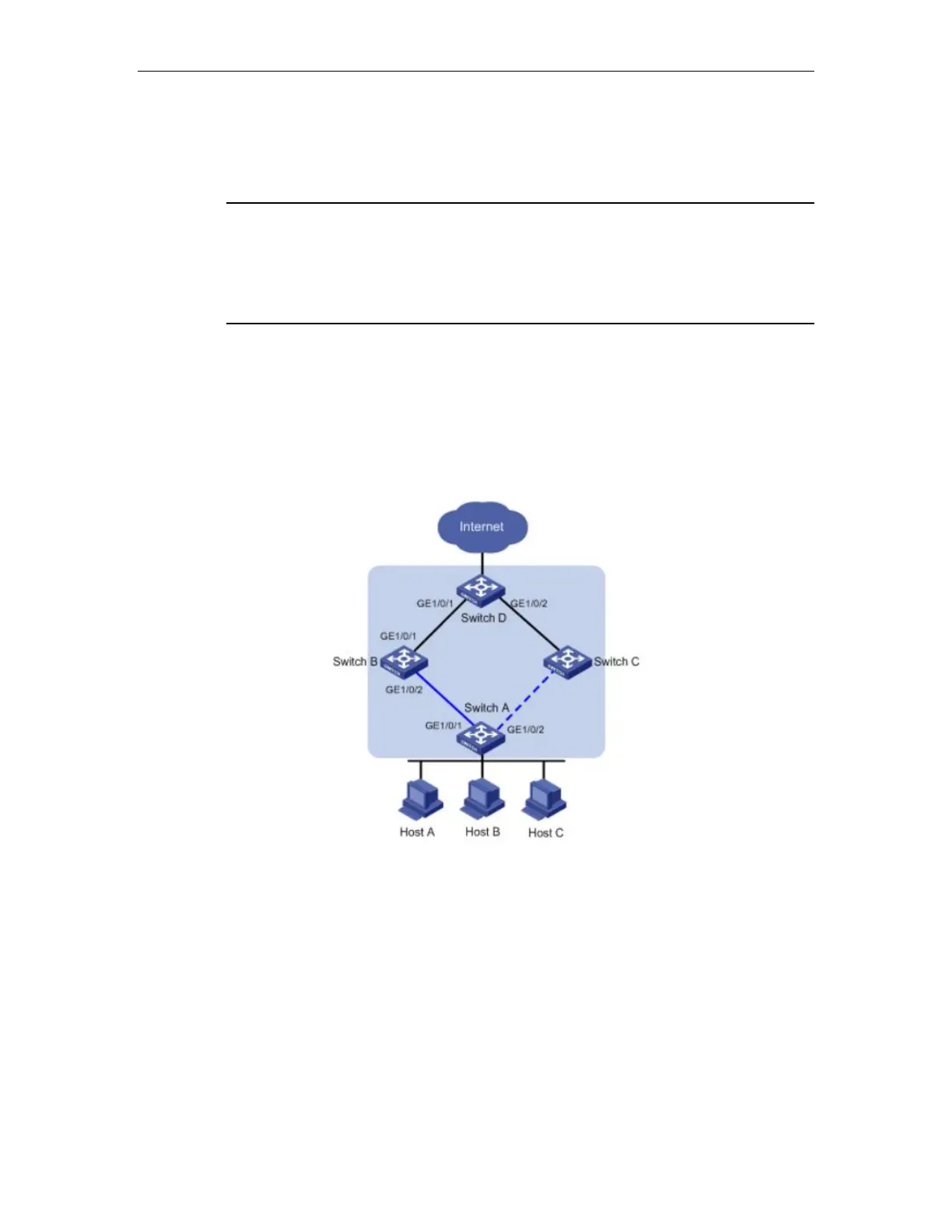
As shown in Figure 33-3, to provide reliable access to the Internet for the hosts, a Flex link
group is configured on Switch A. GigabitEthernet 1/0/1 is the master port of the Flex link
group, and is in the forwarding state. GigabitEthernet 1/0/2 is the slave port.
Figure 33-3 Monitor Link mechanism
To avoid traffic interruption due to the failure of the link on which GigabitEthernet 1/0/1 of
Switch B resides, configure a monitor link group on Switch B, and specify GigabitEthernet
1/0/1 as the uplink port, and GigabitEthernet 1/0/2 as the downlink port.
When the link on which GigabitEthernet 1/0/1 of Switch B resides fails, the monitor link
group shuts down its downlink port GigabitEthernet 1/0/2, triggering a link switchover in the
Flex link group configured on Switch A.
When the link on which GigabitEthernet 1/0/1 of Switch B resides recovers, the downlink
port GigabitEthernet 1/0/2 is also brought up, triggering another link switchover in the Flex link
 Loading...