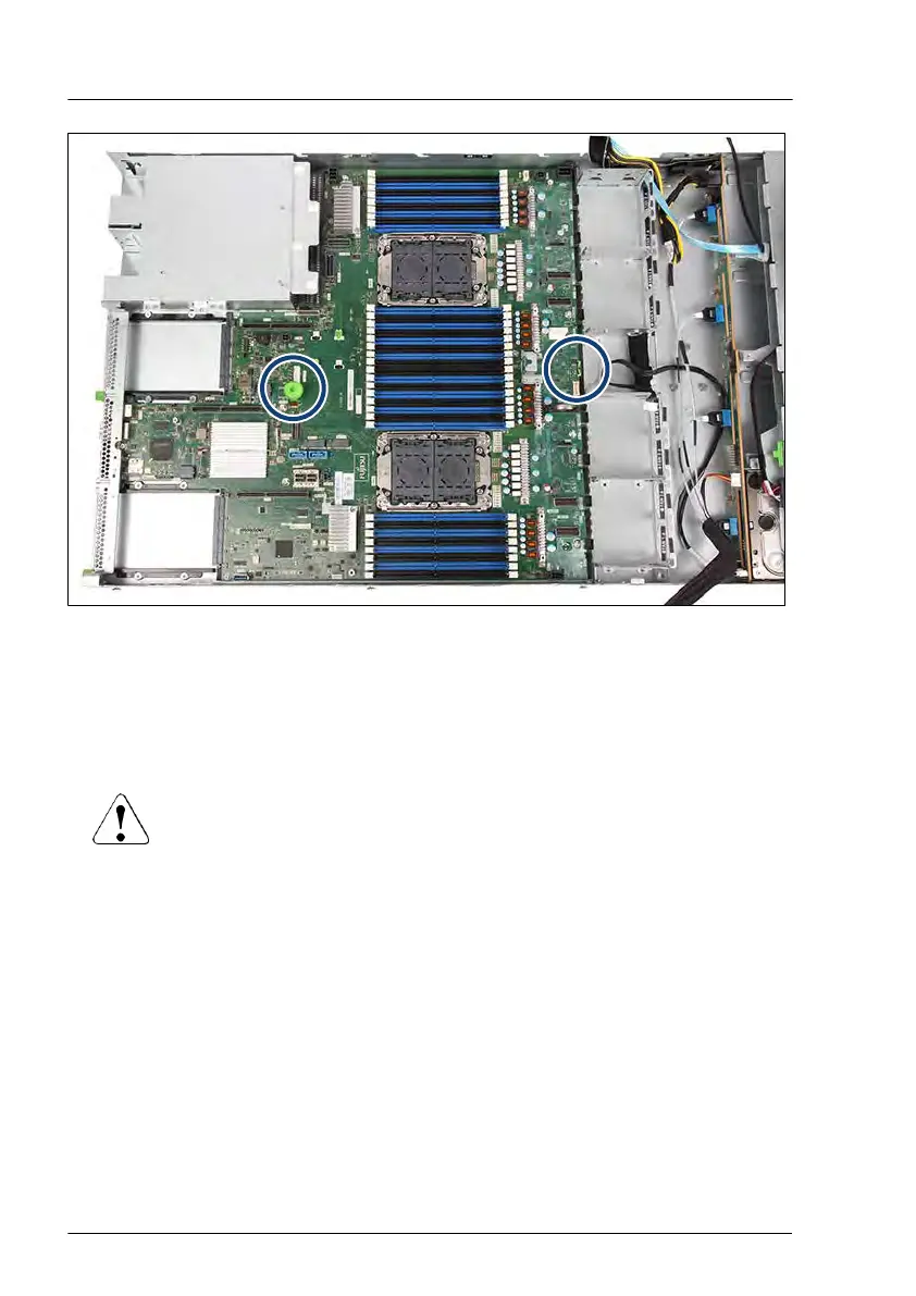
Figure 284: Touch points of the system board
▶
Notice the two points of the system board (see circles).
▶
Hold the system board on the two touch points and lift the system board
carefully out of the chassis in a slight angle. Thereby you pull the connectors
out of the I/O panel.
CAUTION
▶
Always take the system board with both hands!
▶
Never lift the system board one-sided or at a heat sink,
because the solder connections between the socket and the
system board come under tension and increase the risk of
damage and malfunction!
▶
Do not damage the EMI springs which are essential to comply
with applicable EMC regulations and satisfy cooling
requirements and fire protection measures.
▶
Place the removed and the new system board on an antistatic surface.
▶
Remove the TPM, see "Removing the TPM" on page 356.
System board and components
392 Upgrade and Maintenance Manual RX2530 M6

 Loading...