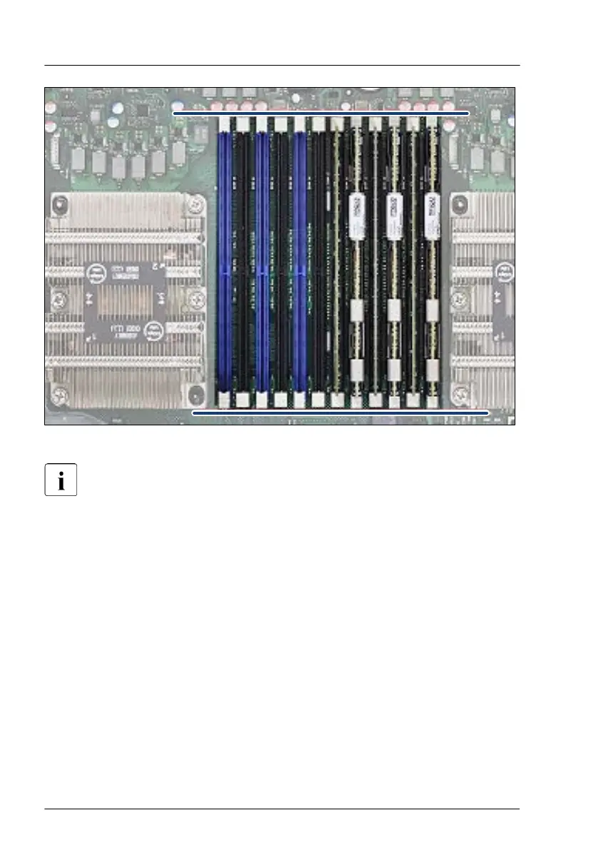
Figure 142: Correct position of securing clips
To improve the contact of the memory module perform the following
steps:
▶
Eject the memory module again by pressing out the securing clips at each
end of the memory slot.
▶
Press down on the memory module until the securing clips snap into the
cutouts at each end of the module.
▶
Check if all securing clips are in the correct position, see Figure 142.
Concluding steps
For memory slots on the bottom system board:
▶
"Installing the air duct 2 (bottom system board)" on page 72
.
▶
"Installing the top system board carrier" on page 76.
▶
"Installing the air duct 1 (top system board)" on page 71.
Main memory
246 Upgrade and Maintenance Manual RX4770 M6
 Loading...