SECTION 4: Repair
2025653-048 Revision B Responder
™
2000 Page 38
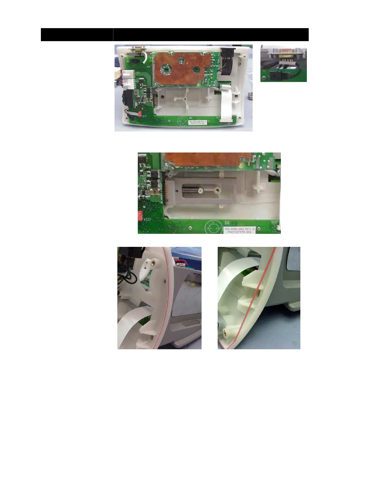
Assembly Step Details
Secure the Power Control
Board with five Phillips
screws.
Place the Service
Connector (serial
connector) on the Lower
Frame.
Note: Pin 1 must be at the
top.
Route and connect all
cables as shown.
Note: See the Ribbon
Cable Installation Notes for
proper installation (Figures
6, 7 and 8).
Figure 30: Power Control Board Installed
Figure 31:
Service Connector
(Correct
Orientation)
Install the Battery Release
and extension spring.
Note: To help the Battery
Release slide under the
Power Control board,
back off the screws holding
the Power Control board a
turn or two and then
retighten after installation.
Figure 32: Battery Release Installed
If necessary, reinstall
rubber tubing along the
edge of the Lower Frame.
Two lengths are required:
• 705 mm ± 3 mm
(27-3/4 in ± 1/8 in)
• 148 mm ± 2 mm
(5-15/16 in ± 1/16 in)
Note: Do not stretch the
tubing as it is inserted into
the groove.
Note: The gap between the
end of the groove and the
start of the tubing must be 2
mm (1/16 in) or less.
Figure 33: Tubing Properly Installed
Figure 34: Tubing Not Properly
Installed