SECTION 4: Repair
2025653-048 Revision B Responder
™
2000 Page 39
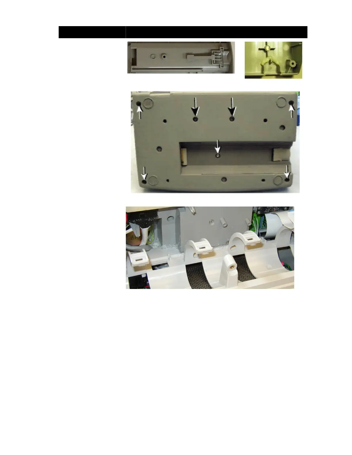
Assembly Step Details
Install the Battery Latch in
the Base Cover.
Apply Silicone to the notch
for the AC power plug.
Figure 35: Battery Latch
Figure 36: Silicone Applied
Install the Base Cover to
the Lower Frame. Using
five Torx security screws
(white arrows).
Note: Tighten the screws
slowly and evenly to ensure
the rubber tubing is seated
correctly and no wires are
pinched.
When all screws are
tightened, check for any
gaps or bulges in the seal.
Install the two larger Torx
security screws (black
arrows) to hold the Power
Supply in place.
Install the four rubber feet if
necessary.
Figure 37: Base Cover
If necessary, check the joint
between the Lower Frame
and the Front Body for
gaps in the silicone. Add
more silicone if necessary.
Figure 38: Front Body and Lower Frame Joint
(with Correctly Applied Silicone)