When the control stick is moved and the green line
moves off the green point, the point will turn red,
the ? is replaced with a number, and the point val-
ue appears in the value field to the right of the sup-
port point number:
PHASE 1 THR.CRV
BACK
IN
OUT
POINT
OFF
INC
ENT
DEC
Y-axis
X-axis
ST ON
CURVE
+050%
+050%
+050%
1
SERVO
The 5 support points between the L and H end-
points can be created in any order; support points
are automatically renumbered sequentially from
left to right after points are set or deleted. In the
example below, the red point at left near the L end-
point is now considered Point 1:
PHASE 1 THR.CRV
BACK
IN
OUT
POINT
OFF
INC
ENT
DEC
Y-axis
X-axis
ST ON
CURVE
–050%
–050%
–025%
1
SERVO
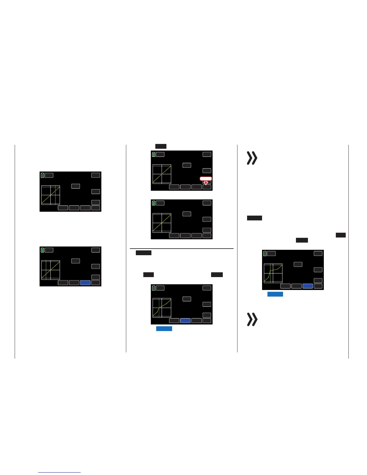
Deleting a Support Point
To remove a set support point, move the control
stick until the vertical green line aligns with the
point to be deleted. The support point will turn red
and its number and associated value will appear in
the POINT line.
Press the ENT button to remove the point:
PHASE 1 THR.CRV
BACK
IN
OUT
POINT
OFF
INC
ENT
DEC
Y-axis
X-axis
ST ON
CURVE
000%
000%
+050%
2
SERVO
Press
The red point disappears:
PHASE 1 THR.CRV
BACK
IN
OUT
POINT
OFF
INC
ENT
DEC
Y-axis
X-axis
ST ON
CURVE
000%
000%
000%
?
SERVO
Changing the Support Point Value
• X-axis Button (X-axis)
Activate this function, press to highlight the button
at the bottom edge of the display.
Move the active (red) point to the right by pressing
the INC button or to the left with the DEC but-
ton, as shown below:
PHASE 1 THR.CRV
SERVO
BACK
IN
OUT
POINT
OFF
INC
ENT
DEC
Y-axis
X-axis
ST ON
CURVE
000%
+018%
000%
2
Press the X-axis button again to deactivate the
function.
Notices
• Moving the red point horizontally away
from thecurrentcontrol position will cause
the point to become green after a short
while, and a ? will appearin the Point line.
This question mark does not relate to the
point which has been moved, rather, it in-
dicates that another point can be set at the
current control position.
• Remember that the percentages in the in-
put (IN) and output (OUT) line always refer
to the temporary position of the control
stick and not to the position of the point.
• Y-axis Button (Y-axis)
Activate this function, press to highlight the button
at the bottom edge of the display.
Move the active (red) point up by pressing the INC
button or down with the DEC button, as shown
below:
PHASE 1 THR.CRV
SERVO
BACK
IN
OUT
POINT
OFF
INC
ENT
DEC
Y-axis
X-axis
ST ON
CURVE
–030%
+035%
+067%
2
Press the Y-axis button again to deactivate the
function.
Notice
Remember that the percentages in the input
(IN) and output (OUT) line always refer to the
momentary position of the control stick and
not to the position of the point.
130 Function menu | general - Curve CH 1

 Loading...


