Notice
The sequencing examples shown are for
demonstration purposes only and do not rep-
resent real servo sequence movements.
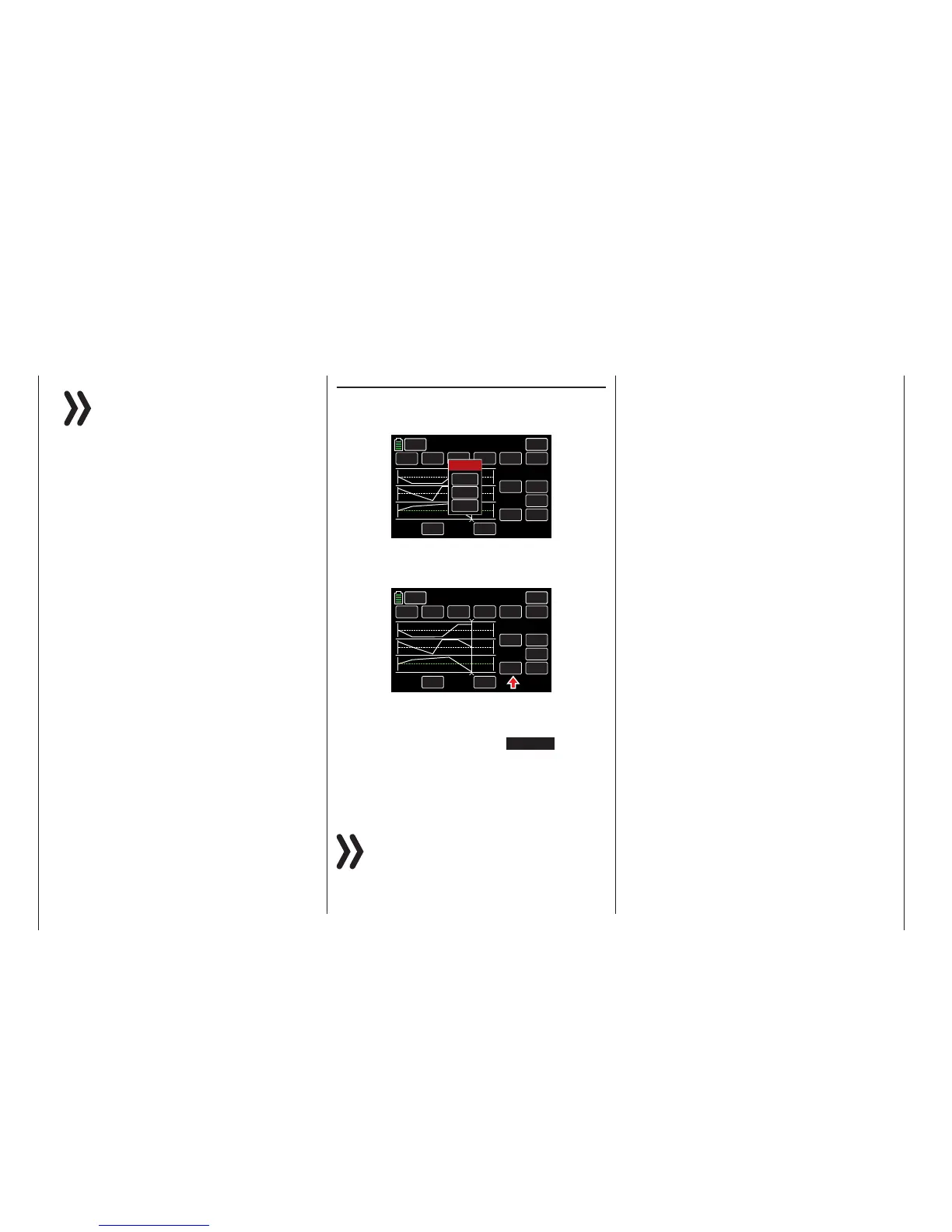
Switch Assignment
To assign an activation switch to the completed se-
quence, follow the instructions in the Control and
Switch Assignment section (page 26):
ON
23.0s
INC
RES
DEC
+100
6
NULL
TIME
POS
ON
BACK
SERVO
Sequence
CH 7 ON
CH 8
CH 6
STEP
CTL
Select
CLR
NO
LOGIC
Use the switch to change between the output and the
target positions of the servos. In the example below,
S6 is assigned in the CTL column:
ON
23.0s
INC
RES
DEC
+100
6
SW 6
TIMER
POS
ON
BACK
SERVO
Sequence
CH 7 ON
CH 8
CH 6
STEP
CTL
When the switch is in the CLOSED position, the se-
lected servos sequence movement can be followed
in the servo monitor. Bring up the servo monitor in
one of three ways: pressing the SERVO button in
the upper right corner of the display, by simultane-
ously pushing both arrow keys ( pq ), or by pressing
the BASE submenu Servo icon. When the switch is
OPEN, all the movements will be reversed.
Notices
• The POS value field input settings are overlap-
ping the common control signals. Before pro-
gramming a sequencer in the BASE submenu
Servo, carefully check that none of the chan-
nels involved in the planned sequence are as-
signed to any transmitter control element. The
action on those controls may lead to process
malfunction.
• Make sure that the servos do not strike any-
thing when preparing and setting a sequenc-
er. Use the BASE submenu E.P.A (page 62)
for fine-tuning these end-point adjustments.
152 Function menu | general - Sequencer

 Loading...


