Notice
If you switch this function OFF via an as-
signed switch, not only is the phase trim de-
activated, but also the functions described in
the Programming section (page 196) under ACT
= INH or OFF.
Lines RATE A / B
A symmetrical or an asymmetrical effect can be de-
fined for each flap pair. In the BASE submenu CTL
Set, leave the assigned switch travel settings for the
flap trimming at +100 %. Then in this display, input
values within 5 and 20 %.
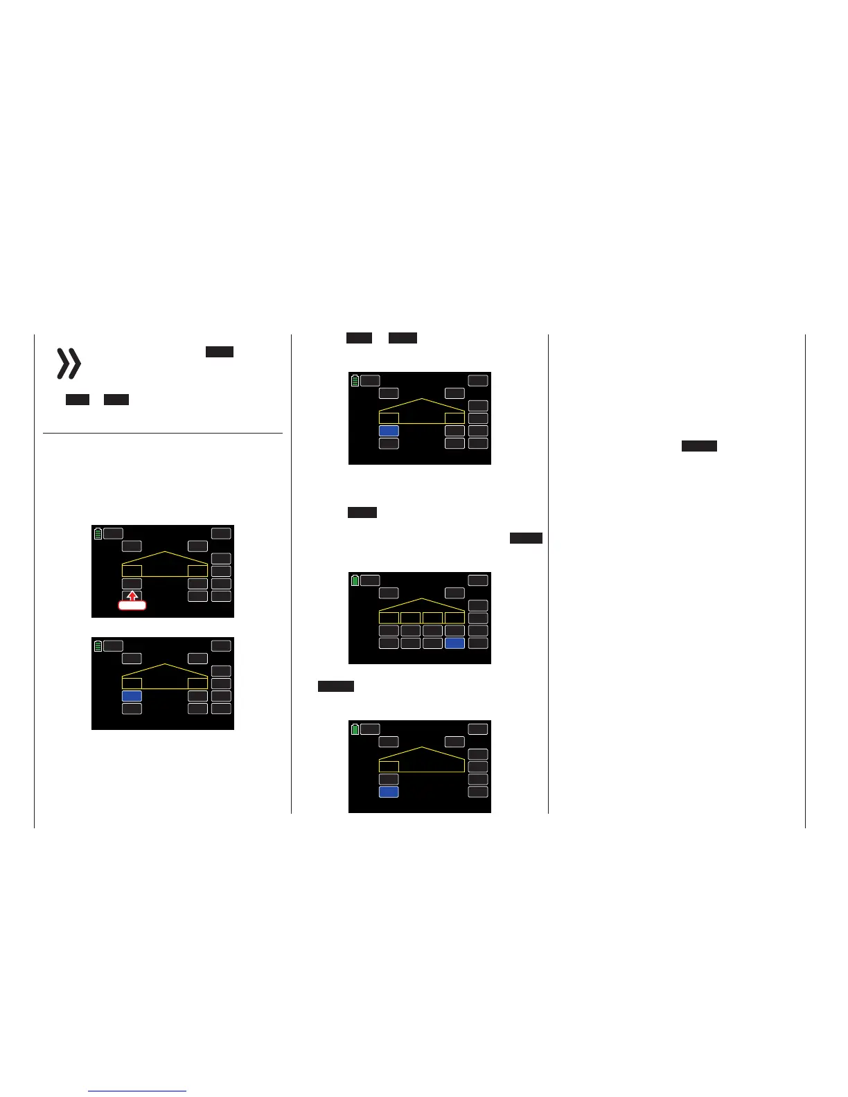
Switch to the appropriate phase, and press the value
field to be changed:
INC
RES
DEC
000%
000%
000%
000%
AILE1 AILE2
ON
ACT CTL
NEXT
SW 6
RATE A
RATE B
BACK
THERMAL Flap set
SERVO
Press
The field highlights blue:
INC
RES
DEC
000%
000%
000%
000%
AILE1 AILE2
ON
ACT CTL
NEXT
SW 6
RATE A
RATE B
BACK
THERMAL Flap set
SERVO
Press the INC or DEC buttons or the arrow keys
( pq ) to increase/decrease the value current value
within a range of ±100%:
INC
RES
DEC
000%
+010%
000%
000%
AILE1 AILE2
ON
ACT CTL
NEXT
SW 6
RATE A
RATE B
BACK
THERMAL Flap set
SERVO
Use the same procedure to adjust the other values
for all remaining fields, including inboard aileron
AILE2L and AILE2R.
Press the RES button to reset the changed value
back to the default.
To bring up the flaps setting screen, press the NEXT
button at the right edge of the display. Use the same
procedure described above to adjust all value fields:
INC
RES
DEC
+020%
+020%
+020%
+020%
ON
ACT CTL
NEXT
SW 6
RATE A
RATE B
BACK
THERMAL Flap set
SERVO
FLAP1 FLAP2
FLAP3
FLAP4
+025%
+025%
+025%
+025%
To bring up the elevator setting screen, press
the NEXT button at the right edge of the display.
Use the same procedure described above to adjust
all value fields:
ON
SW 6
BACK
THERMAL Flap set
SERVO
INC
RES
DEC
+005%
+005%
ELEV1
ACT CTL
NEXT
RATE A
RATE B
Tip
Typically, in the BASE submenu CTL Set, no control is
assigned to the inputs CH5-CH12. Assign a control or
switch to set different flap positions within a phase as
described in this section. By contrast, the Programming
Example Phase Specific Flaps Trimming section
(page 230) describes how to trim the flaps specifically
for all phases through only one control element.
To save and exit, press the BACK button at the top
left of the display to return to the previous menu.
198 Function menu | Airplane models - Flaps settings

 Loading...


