7-10 7. CHINO
7.1.4 LT300 (MODBUS RTU)
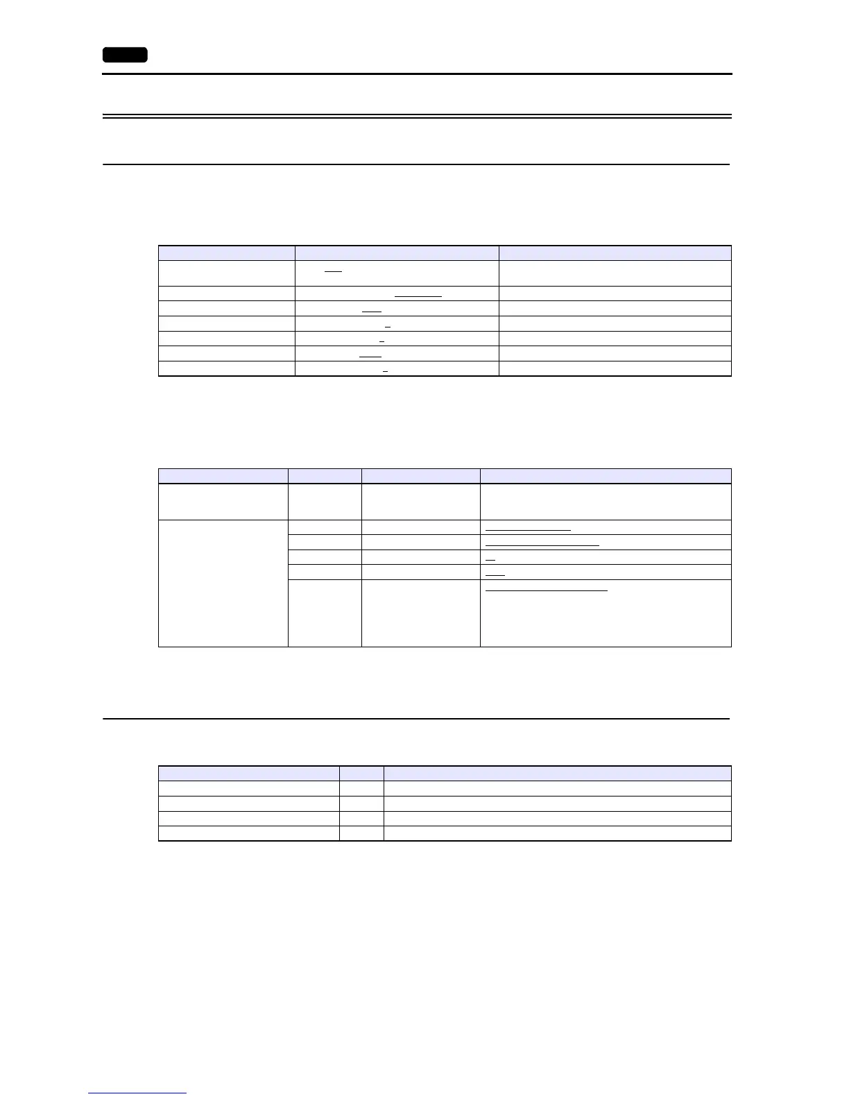
Communication Setting
Editor
Communication setting
(Underlined setting: default)
Digital Indicating Controller
The communication parameters can be set using keys attached to the digital indicating controller.
Be sure to match the settings to those made under [Communication Setting] of the editor.
(Underlined setting: default)
* When changing parameters from the V series, set “LoCK (key lock): 4”.
Available Device Memory
The available setting range of device memory varies depending on the model. Be sure to set within the range available for the
model to be used. Use [TYPE] when assigning indirect device memory for macro programs.
Indirect Device Memory Designation
For the device memory address number, specify the value obtained by subtracting “1” from the actual address.
Item Setting Remarks
Connection Mode
1:1 / 1:n
/ Multi-link2 / Multi-link2 (Ethernet) /
1:n Multi-link2 (Ethernet)
Signal Level RS-232C / RS-422/485
Baud Rate 9600 / 19200 bps
Data Length 8
bits
Stop Bit 1
/ 2 bits
Parity None
/ Odd / Even
Targe t Por t N o. 1
to 99
Mode Indication Item Setting
Mode 1
eng (engineering)
LoCK Key lock
4: All items prohibited
*
Mode 7
com (communication setting)
PtCL Communication protocol rtU: MODBUS (RTU)
FUnC Communication function Com: Host communication
AdrS Device No. 01 to 99
rAtE Baud rate 9600
/ 19200 bps
CHAr
Character
(Data length, parity,
stop bit)
5: 8 bits / without parity / 1 bit
6: 8 bits / without parity / 2 bits
7: 8 bits / even parity / 1 bit
8: 8 bits / even parity / 2 bits
9: 8 bits / odd parity / 1 bit
10: 8 bits / odd parity / 2 bits
Device Memory TYPE Remarks
4 (analog setting value) 00H
3 (analog input data) 01H Read only
0 (digital setting value) 02H
1 (digital input data) 03H Read only