7.1 Temperature Controller/Servo/Inverter Connection 7-13
7.1.7 KR2000 (MODBUS RTU)
Communication Setting
Editor
Communication setting
(Underlined setting: default)
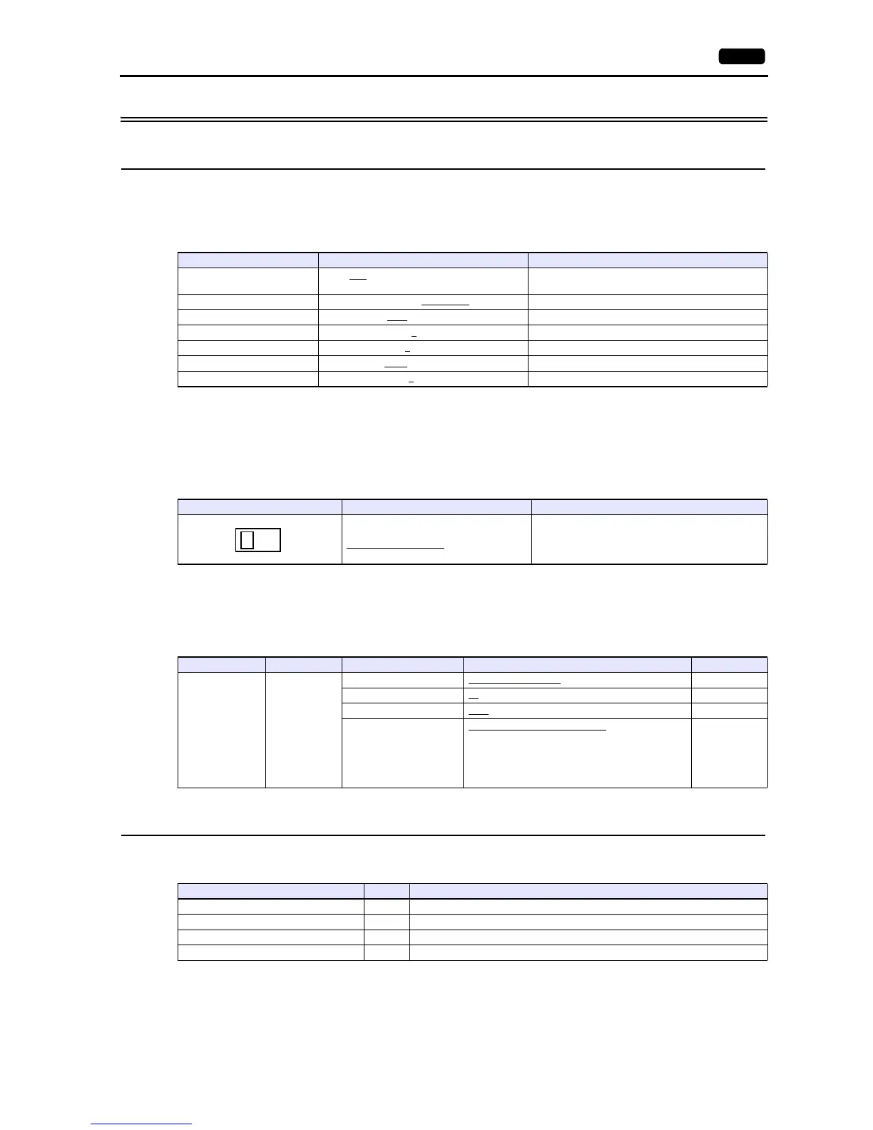
Graphic Recorder
Selector switch
When establishing a communication with a graphic recorder, set the selector switch at the top of the unit.
(Underlined setting: default)
Communication setting
The communication parameters can be set using MENU keys attached to the graphic recorder.
Be sure to match the settings to those made under [Communication Setting] of the editor.
(Underlined setting: default)
Available Device Memory
The available setting range of device memory varies depending on the model. Be sure to set within the range available for the
model to be used. Use [TYPE] when assigning indirect device memory for macro programs.
Indirect Device Memory Designation
For the device memory address number, specify the value obtained by subtracting “1” from the actual address.
Item Setting Remarks
Connection Mode
1:1 / 1:n
/ Multi-link2 / Multi-link2 (Ethernet) /
1:n Multi-link2 (Ethernet)
Signal Level RS-232C / RS-422/485
Baud Rate 9600 / 19200 bps
Data Length 8
bits
Stop Bit 1
/ 2 bits
Parity None
/ Odd / Even
Targe t Por t N o. 1
to 31
Selector switch Setting Remarks
232C: RS-232C connection
485: RS-485 connection
Switch the signal with the power to the recorder OFF.
Setting Menu Menu Item Setting Remarks
System setting
Host
communication
Communication mode RTU: MODBUS (RTU)
Device address 01 to 31
Bit rate 9600
/ 19200 bps
Communication characters
(Data length, parity,
stop bit)
8N1: 8 bits / without parity / 1 bit
8N2: 8 bits / without parity / 2 bits
8E1: 8 bits / even parity / 1 bit
8E2: 8 bits / even parity / 2 bits
8O1: 8 bits / odd parity / 1 bit
8O2: 8 bits / odd parity / 2 bits
Device Memory TYPE Remarks
4 (analog setting value) 00H
3 (analog input data) 01H Read only
0 (digital setting value) 02H
1 (digital input data) 03H Read only