1.3 Connection Methods 1-15
PLC properties
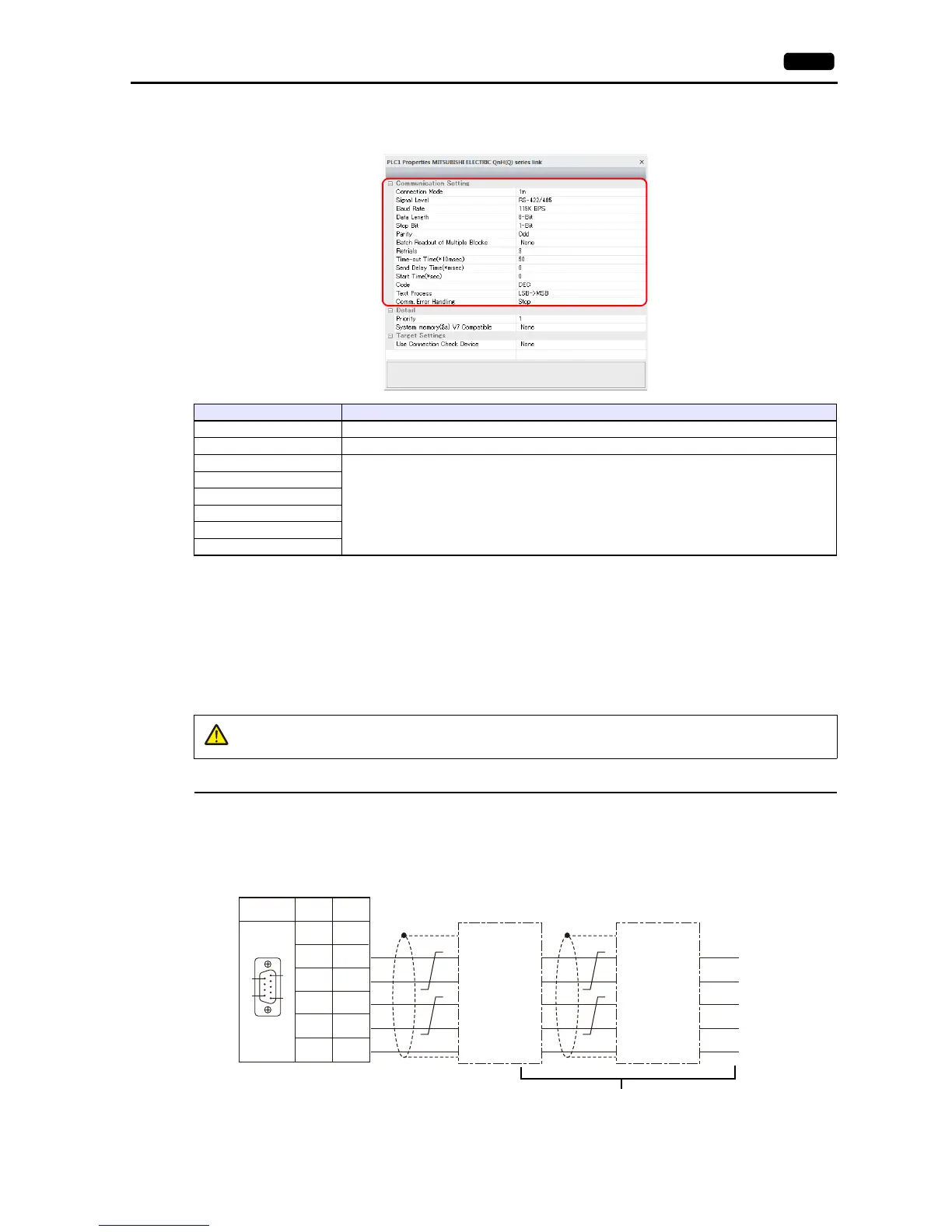
Configure [Communication Setting] on the [PLC Properties] window.
For settings other than the above, see “1.4 Hardware Settings” (page 1-43).
Settings of a Connected Device
Refer to the chapter of the respective manufacturer.
For descriptions of connecting PLCs, refer to the manual for each PLC.
Wiring
CN1
The wiring between a V9 and a connected device is the same as that for 1 : 1 communication. For description of wiring
between connected devices, refer to the manuals issued by the manufacturers.
RS-422 (4-wire system) connection
Connection example
Item Contents
Connection Mode 1 : n
Signal Level RS-422/485
Baud Rate
Configure according to the connected device.
Data Length
Stop Bit
Parity
Target Po r t N o.
Transmission Mode
RS-422 port of the
connected device
Send data ()
Receive data (+)
Send data (+)
Receive data ()
RS-422 port of the
connected device
Send data ()
Receive data (+)
Send data (+)
Receive data ()
Terminating resistance ON
For wiring between connected devices, refer
to the manuals issued by the manufacturers.