1-24 1. Overview
Terminating Resistance Setting
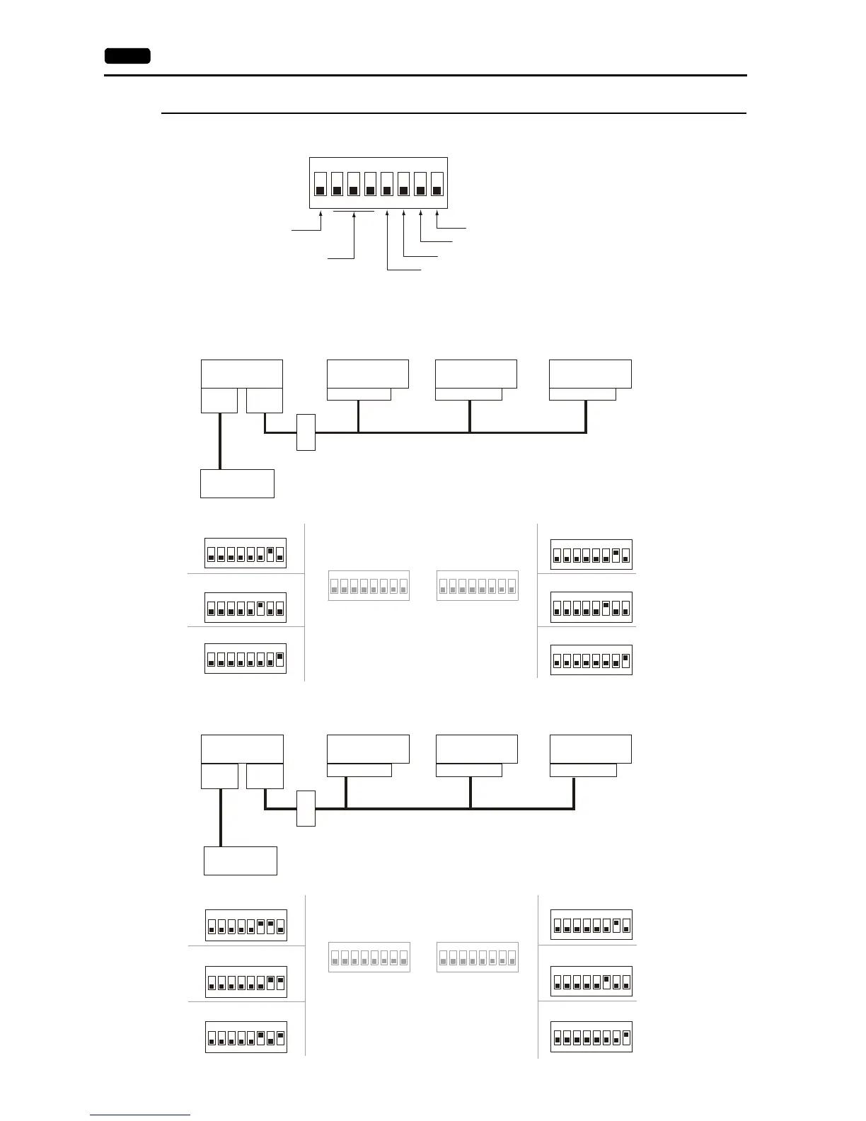
The terminating resistance should be set on the DIP switch.
When the PLC is connected to the master via RS-232C:
There is no terminating resistance setting for communications between the master and the PLC. Set terminating resistances
for connections between V9 units.
When the PLC is connected to the master via RS-422/485:
Make terminating resistance settings for communications between the master and PLC, and between V9 units.
Automatic upload to storage
Terminating resistance of MJ2
Not used
+RD/-RD terminating resistance of CN1
Terminating resistance of MJ1
+SD/-SD terminating resistance of CN1
RS-232C
ON
12345678
ON
12345678
ON
12345678
ON
12345678
ON
12345678
PLC
CN1/MJ1/MJ2 CN1/MJ1/MJ2 CN1/MJ1/MJ2
CN1
MJ1/2
CN1
MJ1/2
ON
12345678
ON
12345678
ON
12345678
RS-485 (2-wire system)
Master
(= Local port 1)
Slave
(= Local port 2)
Slave
(= Local port 3)
Slave
(= Local port 4)
Ter min al
block
When MJ1 is used:
When CN1 is used:
When MJ2 is used:
When MJ1 is used:
When CN1 is used:
When MJ2 is used:
RS-422/485
ON
12345678
ON
12345678
ON
12345678
ON
12345678
ON
12345678
PLC
CN1
MJ1/2
CN1
MJ1/2
CN1/MJ1/MJ2 CN1/MJ1/MJ2 CN1/MJ1/MJ2
ON
12345678
ON
12345678
ON
12345678
RS-485 (2-wire system)
Master
(= Local port 1)
Slave
(= Local port 2)
Slave
(= Local port 3)
Slave
(= Local port 4)
Ter min al
block
When CN1 and MJ2 are used:
When MJ1 and MJ2 are used:
When CN1 and MJ1 are used:
When MJ1 is used:
When CN1 is used:
When MJ2 is used: