19.1 PLC Connection 19-1
19.1 PLC Connection
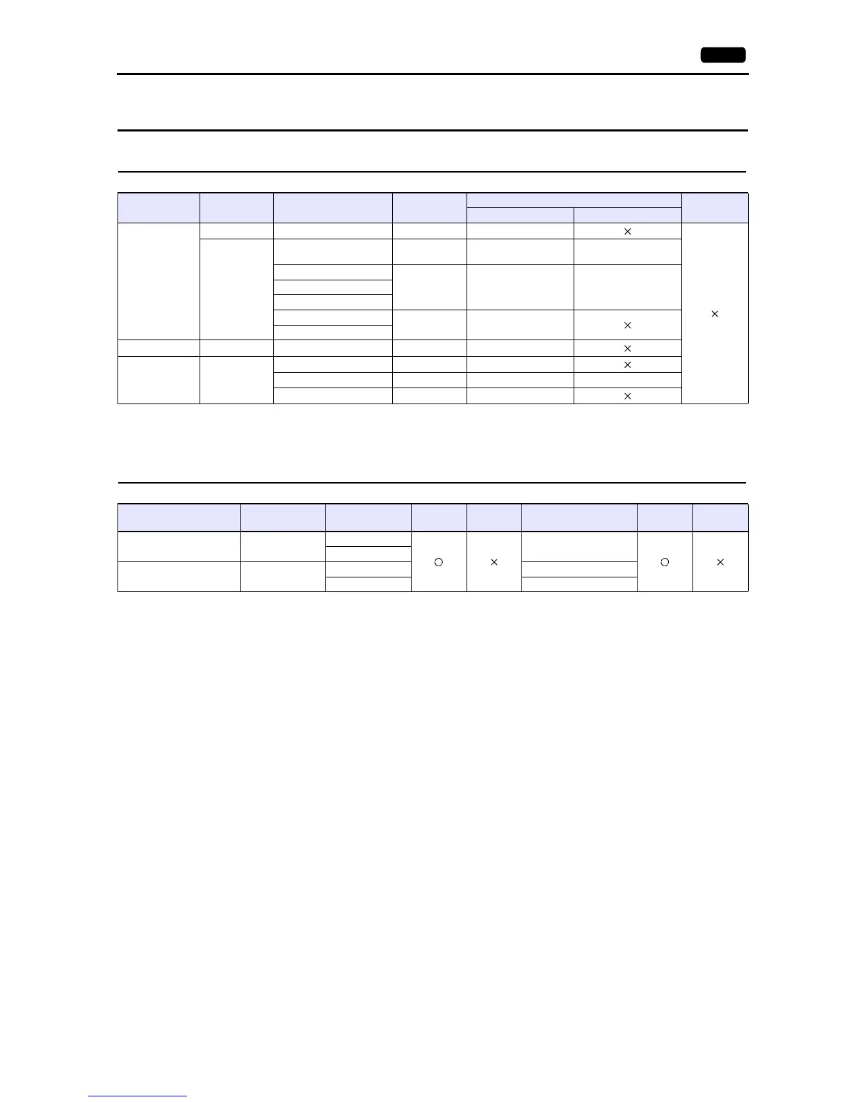
Serial Connection
*1 For the ladder transfer function, see the V9 Series Reference Manual.
Ethernet Connection
*1 For KeepAlive functions, see “1.3.2 Ethernet Communication”.
*2 For the ladder transfer function, see the V9 Series Reference Manual.
PLC Selection on
the Editor
CPU Unit/Port Signal Level
Connection
Ladder
Transfer
*1
CN1 MJ1/MJ2
HIDIC-S10/2
S10mini
S10 2 Interface on the CPU unit RS-422 Wiring diagram 1 - C4
LQP000
LQP010
LQP011
LQP120
RS-232C connector on the
CPU unit
RS-232C Wiring diagram 1 - C2 Wiring diagram 1 - M2
LQE060 (CN1, CN2)
RS-232C Wiring diagram 2 - C2 Wiring diagram 2 - M2LQE160 (CN1, CN2)
LQE560 (CN1, CN2)
LQE165 (CN1, CN2)
RS-422 Wiring diagram 2 - C4
LQE565 (CN1, CN2)
HIDIC-S10/4 S10 4 LWE805 RS-422 Wiring diagram 1 - C4
HIDIC-S10V LQP510
UP LINK RS-422 Wiring diagram 2 - C4
LQE560 (CN1, CN2) RS-232C Wiring diagram 2 - C2 Wiring diagram 2 - M2
LQE565 (CN1, CN2) RS-422 Wiring diagram 2 - C4
PLC Selection on the Editor CPU Unit TCP/IP UDP/IP Port No.
Keep
Alive
*1
Ladder
Transfer
*2
HIDIC-S10/2S10mini
(Ethernet)
S10mini
LQE020
4301 (max. 4 units)
LQE520
HIDIC-S10V (Ethernet) LQP510
LQE520 4302 (max. 4 units)
LQP520 4302 to 4305 (1 each)