20.1 PLC Connection 20-11
EH-SIO
PORT1/PORT2
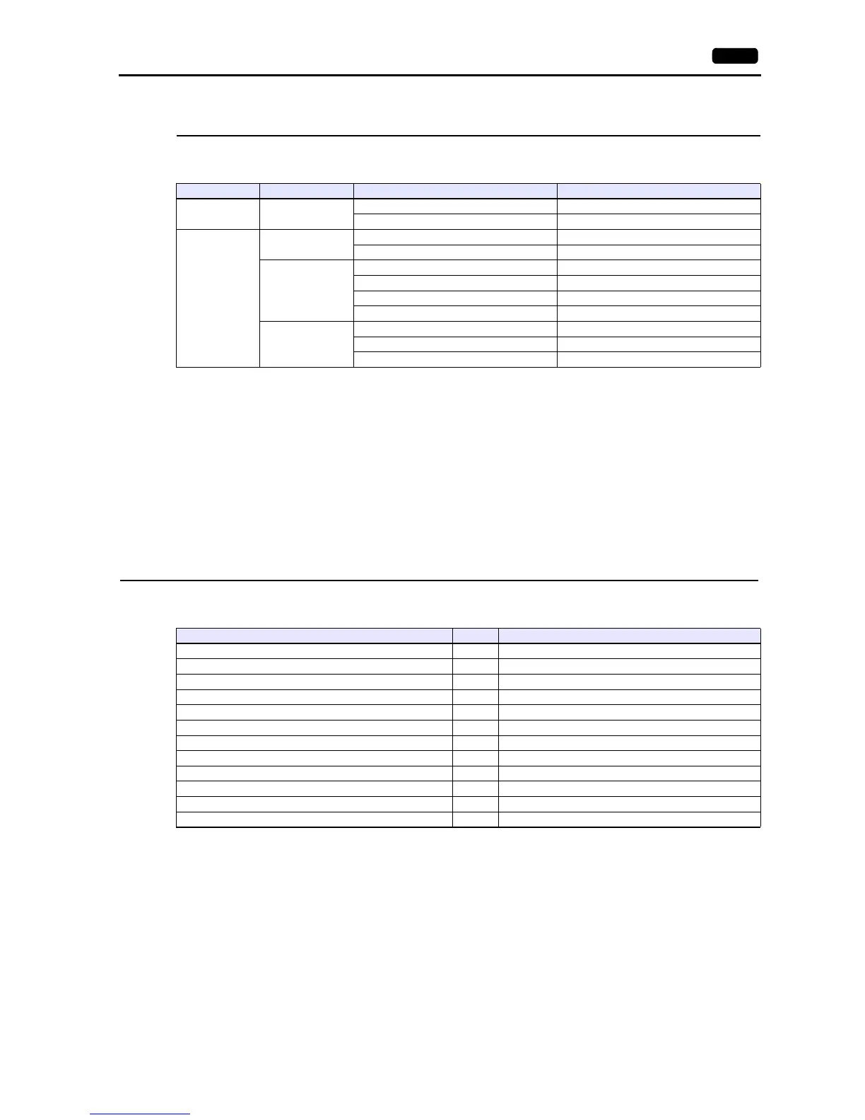
The following table shows the signal level and the communication protocol for each port. Other parameters (7 bits, 1 bit,
even) are fixed.
DIP switch 1/2
Set the baud rate for PORT1/2 using the DIPSW1/2 attached to the side of EH-SIO. For more information, refer to the PLC
manual issued by the manufacturer.
Ladder program
Make initial settings for the transmission control protocol and the station number.
For more information, refer to the PLC manual issued by the manufacturer.
Available Device Memory
The available setting range of device memory varies depending on the PLC model. Be sure to set within the range available for
the PLC to be used. Use [TYPE] when assigning indirect device memory for macro programs.
Port Signal Level Communication Protocol EH-SIO Version
PORT1 RS-232C
Transmission control protocol 1 Version 2.0 and later
Transmission control protocol 2 Version 2.1 and later
PORT2
RS-232C
Transmission control protocol 1 Version 2.0 and later
Transmission control protocol 2 Version 2.1 and later
RS-422
Transmission control protocol 1 Version 2.0 and later
Transmission control protocol 2 Version 2.1 and later
Transmission control protocol 1 with port Version 2.0 and later
Transmission control protocol 2 with port Version 2.1 and later
RS-485
Transmission control protocol 2 Version 2.1 and later
Transmission control protocol 1 with port Version 2.0 and later
Transmission control protocol 2 with port Version 2.1 and later
Device Memory TYPE Remarks
WR (internal output/word) 00H
X (external input) 01H WX as word device
Y (external output) 02H WY as word device
L (CPU link area) 03H WL as word device
M (data area) 04H WM as word device
TC (timer, counter/elapsed time) 05H
R (internal output/bit) 06H
TD (timer, counter/contact) 07H
WN (network input/output) 08H
CL (counter clear) 09H
EX (extensional external input) 0BH WEX as word device
EY (extensional external output) 0CH WEY as word device