20.2 Temperature Controller/Servo/Inverter Connection 20-23
20.2.2 SJ700 Series
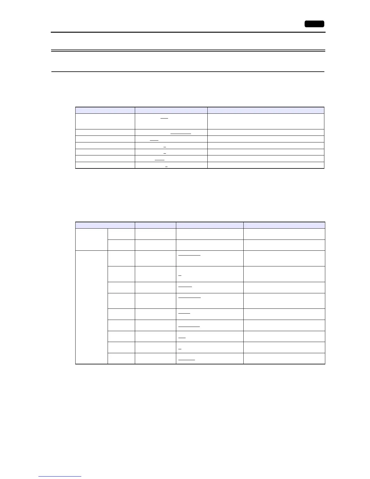
Communication Setting
Editor
Communication setting
(Underlined setting: default)
Inverter
Parameter
The communication parameters can be set using keys attached to the inverter.
Be sure to match the settings to those made under [Communication Setting] of the editor.
(Underlined setting: default)
Terminating resistance
Short-circuit RP-SN (control terminal block) on the terminal inverter.
Item Setting Remarks
Connection Mode
1:1 / 1:n
/ Multi-link2 /
Multi-link2 (Ethernet) /
1:n Multi-link2 (Ethernet)
Signal Level RS-232C / RS-422/485
Baud Rate 4800 / 9600 / 19200 bps
Data Length 7
/ 8 bits
Stop Bit 1
/ 2 bits
Parity None
/ Odd / Even
Targe t Por t N o. 1
to 32
Function Code Function Name Setting Remarks
Basic setting
A001
Frequency
command selection
03: RS-485
To give the frequency command from V9,
always select “03”.
A002
Operation command
selection
03: RS-485
To give the operation command from V9,
always select “03”.
Communicatio
n function
adjustment
C071 Baud rate selection
04: 4800 bps
05: 9600 bps
06: 19200 bps
C072
Communication
station number
selection
1.
to 32.
C073
Communication bit
length selection
7: 7 bits
8: 8 bits
C074
Communication
parity selection
00: No parity
01: Even parity
02: Odd parity
C075
Communication
stop bit selection
1: 1 bit
2: 2 bits
C076
Communication
error selection
02: Ignored
C077
Communication trip
time
0.00
- 99.99 (s)
C078
Communication
latency
0.
- 1000. (ms)
C079
Communication
mode selection
00: ASCII