2.1 PLC Connection 2-9
Available Device Memory
The available setting range of device memory varies depending on the PLC model. Be sure to set within the range available for
the PLC to be used. Use [TYPE] when assigning indirect device memory for macro programs.
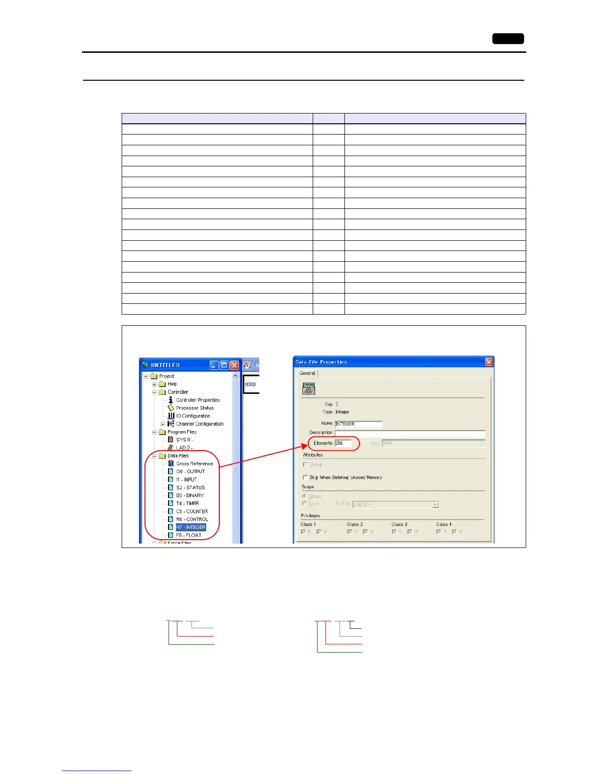
Address denotations
The assigned device memory is expressed as shown below when editing the screen.
Example: For word access For bit access
The file number will not be displayed for the input, output or status device memory.
Device Memory TYPE Remarks
N(integer) 00H
B(bit) 01H
T.ACC (timer/current value) 02H
T.PRE (timer/set value) 03H
C.ACC (counter/current value) 04H
C.PRE (counter/set value) 05H
I(input) 06H
O(output) 07H
S(status) 08H
T(timer/control) 09H
C (counter/control) 0AH
R(control) 0BH
R.LEN (control/data length) 0CH
R.POS (control/data position) 0DH
D(BCD) 0EH
A (ASCII) 0FH
F (FLOAT) 10H Real number
ST (STRING) 11H
Make settings for “Data Files” using the ladder tool. Otherwise, “Error Code F007”, etc. is displayed on MONITOUCH. For
more information, refer to the PLC manual issued by the manufacturer.