2
General information Operating instructions HERMA 400
16/154 3.28 US (130519)
2.2.2 General designations
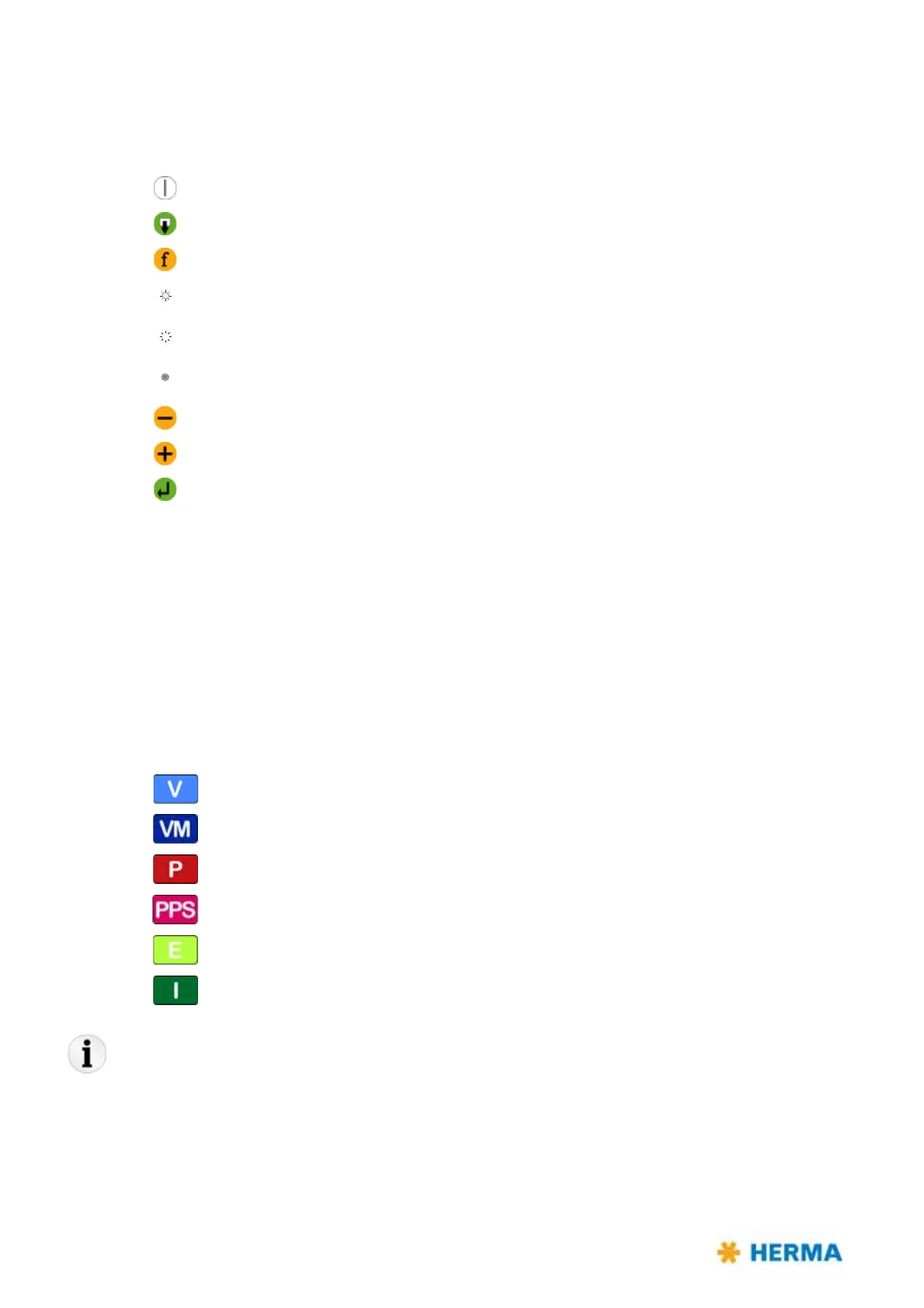
Elements of the HERMA 400 control are designated and depicted in these instructions as follows:
Switch-on key
Manual feed key
Function key
LED (on)
LED (blinks)
LED (off)
Minus key
Plus key
Enter key
Find further explanation on these elements in section 9.1.
The HERMA 400 applicator is configured and offered
as different model types.
The applicator type will be indicated in the basic display image with a corresponding letter, provided,
parameter „915 Ready screen“ is set to 00. See page 122.
Find here an overview of these models / letters and th
e corresponding symbols used in this manual:
Symbol / Abbreviation Type name
Vario
Vario M
Premium
Premium Plus Serial
Econ
Idea
Notes: A few of the illustrations used in this manual are examples and may differ sightly from the
configuration of your applicator.
Furthermore, note that the HERMA 400 applicator is available in both left-hand and right-
hand
versions and that some illustrations may only show one of these versions.