5
Operating instructions HERMA 400 T
ECHNICAL DATA
3.28 US (130519) 77/154
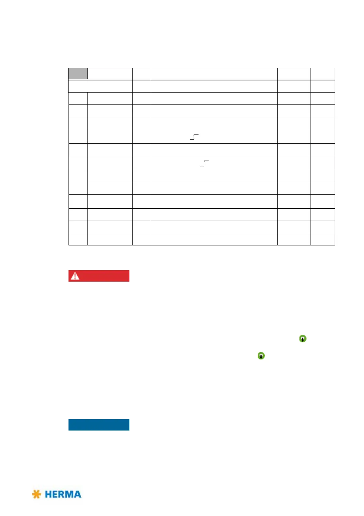
5.3 Inputs / outputs (X19) (option, extended signals)
This optional connector provides inputs/outputs to the external control (e.g. PLC).
Risk of electric shock! Disconnect all sources of supply and wait for five
minutes before opening the rear cover or touching the connector pins!
Electrocution may occur.
** Note: Jumper „Feed“ is not set: Without control via PLC,
Pin 12 and Pin 4 must be bridged in
order to activate the function of the manual feed key.
When using an external control the functionality of the manual feed key
must be
realized via a corresponding logic.
Jumper „Feed“ is set: Manual feed is possible via the key
as well as externally.
††
Note: START (6) possible only if LOCK (9) not active.
For the appropriate pin assignment of further connections, please refer to the
separate wiring diagram.
X19 Designation I/O Description Color
➜97941
PIN
1 +24V out Power supply (<150mA) brown
X31.9
2 Gnd i/o Ground (all voltages DC) blue
X31.2
3 X29.2 in User defined white
X29.2
4 Feed** in
Manual feed
green
X31.5
5 Stop i/o Label sensor (end of transport) pink
X31.4
6
Start
††
in
Start of labeling
yellow
X21.4
7 X29.4 in User defined black
X29.4
8 S3 out Key S3 „function“ grey
X31.6
9
Lock
††
in Lock labeling start (1-active) red
X31.10
10 No_Label out Missing label on web violet
X31.7
11 Feeding out Label transport running greypink
X31.3
12 S2** out Key S2 „manual feed “ redblue
X31.8