6
Transport, installation, storage and connection Operating instructions HERMA 400
84/154 3.28 US (130519)
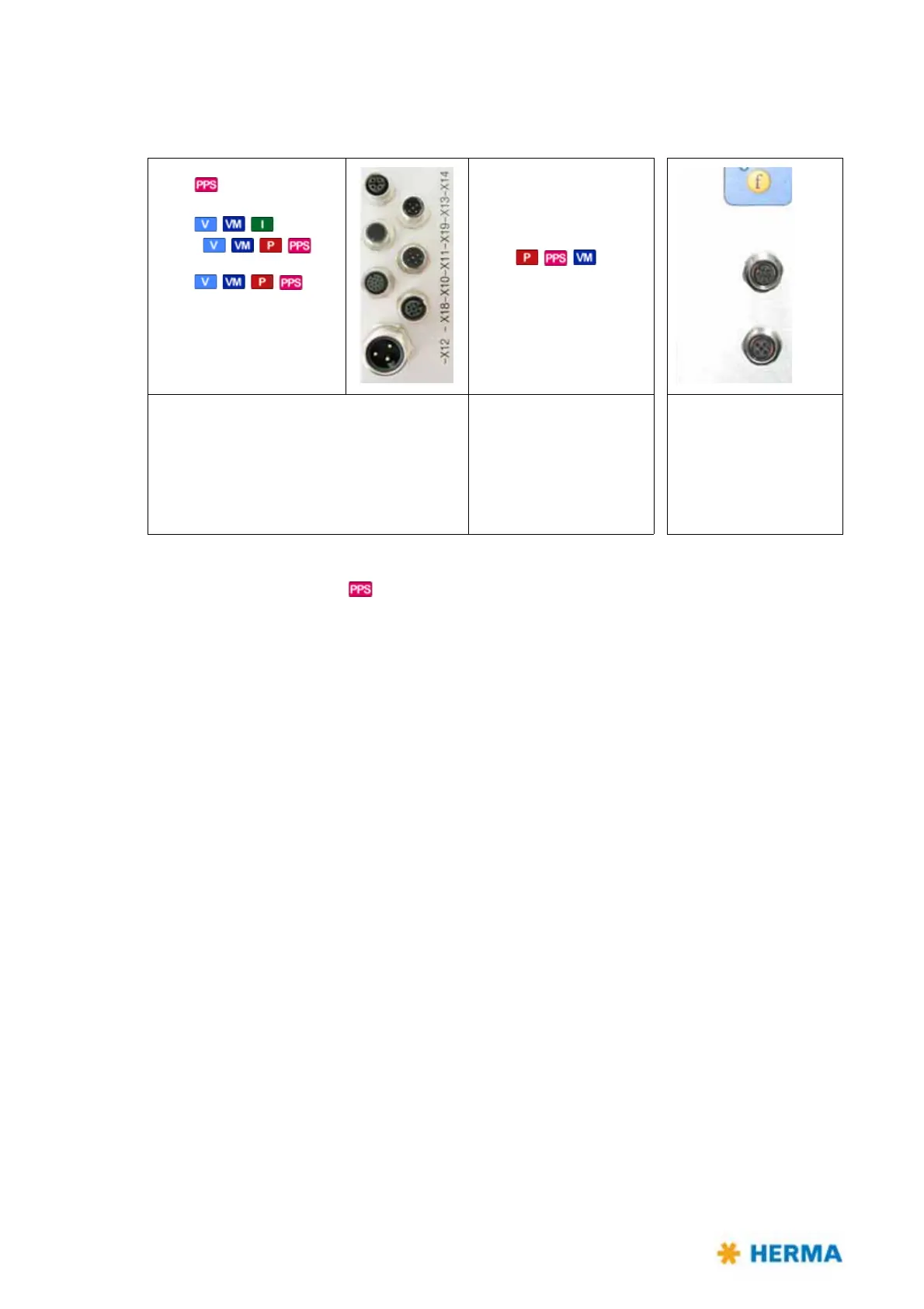
6.4.1 Connections
The following connections are available at the HERMA 400 applicator (depending on the configuration):
X14 – Serial OUT
X16 – Labeling start
X19 – Inputs/Outputs (ext. signals)
X10 – Inputs/Outputs (stand. signals) /
signal column/stack light (optional)
X12 – Power supply
* X16 as special case, if X10/X19 occupied an
d separate start signal required .
Impossible with
.
** X16 as start signal, if X10/X1
9 are free.
†
Must be interrupted before effecting a program update or if initialized for the very first
time.
††
In the standard configuration as of applicator no. 206... pin 5 of the cable from X17 to X3
of the CAN-I/O board is plugged in (a). Furthermore a jumper from pin 7 to pin 8 is set on
X27 (b). Thus the signal „printer running“ / „printer error“ can be interrogated.
X14 (
) /(X16 (special)*)
X16 (,,) /
X19 (,,,)**
X10 (,,,)
X12
X1
3 (all types)
†
X11 (,,)
X18 (all types)
†
Shown here: left-hand version;
right-hand version is mirror-
inverted.
X13 – Serial IN
X11 – Master encoder
X18 – CAN extension
X17 – Transfer /
Printer
††
X15 – Label sensor