4
Applicator description Operating instructions HERMA 400
42/154 3.28 US (130519)
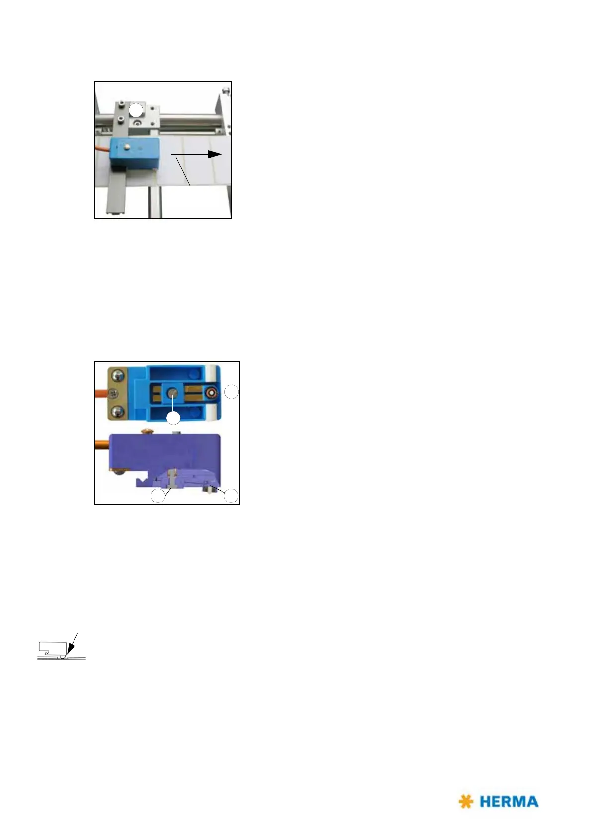
Positioning the label
2
Direction of web
movement
Depending on the application labels have to be peeled off completely
(for suction), or a small part of the label remains
attached to the
backing paper (for tearing off, i.e. the product „takes“ the label), or a
small part of the label is peeled off and most of it remains attached to
the backing paper (for labeling with synchronous parallel motion).
You can adjust the position of the label at the dispensing plate (label
at
tachment) by positioning the sensing unit by means of holder 2 in
or opposite to the direction of the label movement.
This positioning is also called „label overf
eed delay“ or „stop delay“.
With some configurations this delay is set via potentiometer at the
applicator housing (see also section / page 100) or in the control box or even via parameter in the
control program (where applicable).
The order numb
er of the sensor with plug-in connector is printed on the housing.
Replacing the sensing head
Sensing head 3 can be replaced after loosening screw 4.
A basic adjustment is required thereafter (see „Teaching“ in
section „Setting mode“).
Setting mode
In this mode the sensor can learn the thickness of the backing paper and can be set to different label
material (paper labels or electrically conducting labels (metallized or aluminium-covered)). Moreover
an offset can be adjusted, i.e., a little shifting of the switch point which may become necessary under
challenging conditions, e.g. at very high speed.
In order to get to a certain function the set button must remain pressed for different lengths of time.
If, e.g., the function for changing the label material to be sensed is to be called up the button must be
pressed for at least 10 seconds and 15 seconds at the most.
The sensor must be positioned into the gap between the labels.
Note: The buttonpress duration is reset to 0 after ev
ery end of function. The different functions
are indicated via changing states of the LED.
Remark: The following description only
refers to the sensor with material number 680297 (see
imprint on the unit).