9
Operation (via the HERMA 400 control) Operating instructions HERMA 400
100/154 3.28 US (130519)
Display
The display is activated with applying mains and will show one of two possible variants of the basic
display image:
is off is on*
* if parameter 915 is set to ’00’. Other images, however, can be chosen as well. See s
ection 9.12.3 on
page 122.
If used, the format currently loaded is indicated in the right upper corner of the basic display image
(e.g
. „F05“ for format 05). See section 9.10 on page 120.
This basic display image will be shown au
tomatically if no key is pressed at the display for two minutes
or if the user actuates the function key
several times in a menu or in the edit mode.
The applicator type will be indicated in the basic display image with a corresponding letter:
E
(Econ ),
I
(Idea ),
V
(Vario ),
VM
(Vario M ),
P
(Premium ),
PPS
(Premium Plus Serial
).
The current software version is indicated in the next line (this may be required by the Technical
Service).
Inputs for start signal and label sensor ar
e indicated via symbols in the right bottom corner of the
display:
= startsignal is applied, = label sensor currently on label (paper).
For a further description see section 9.5, page 103, and following.
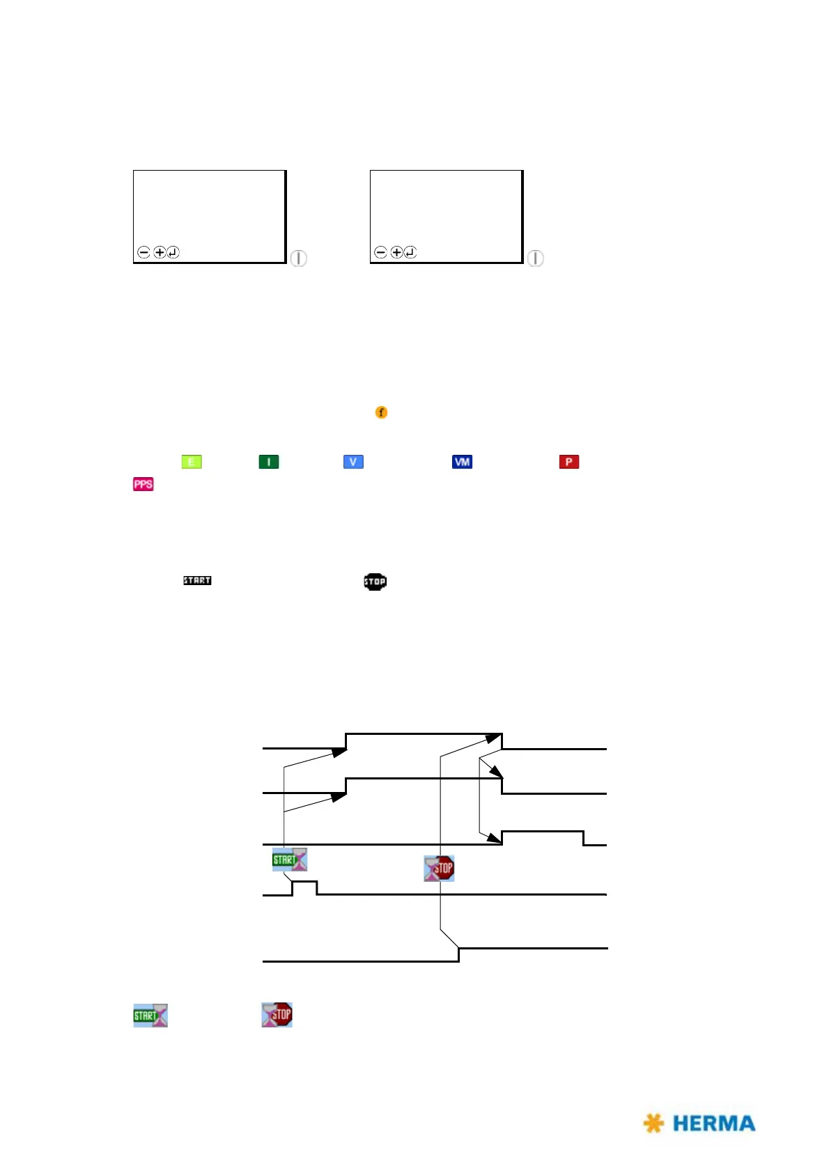
9.2 Function diagram
Functions in the HERMA 400 applicator are as follows (pivot beak and printer are options):
= Start delay, = Stop delay
STANDBY F05
H400 V
Vz.xx.yy
Menu
READY F05
H400 V
Vz.xx.yy
Menu
Transport
Pivot beak
Printer
Start
Stop signal