4
Applicator description Operating instructions HERMA 400
28/154 3.28 US (130519)
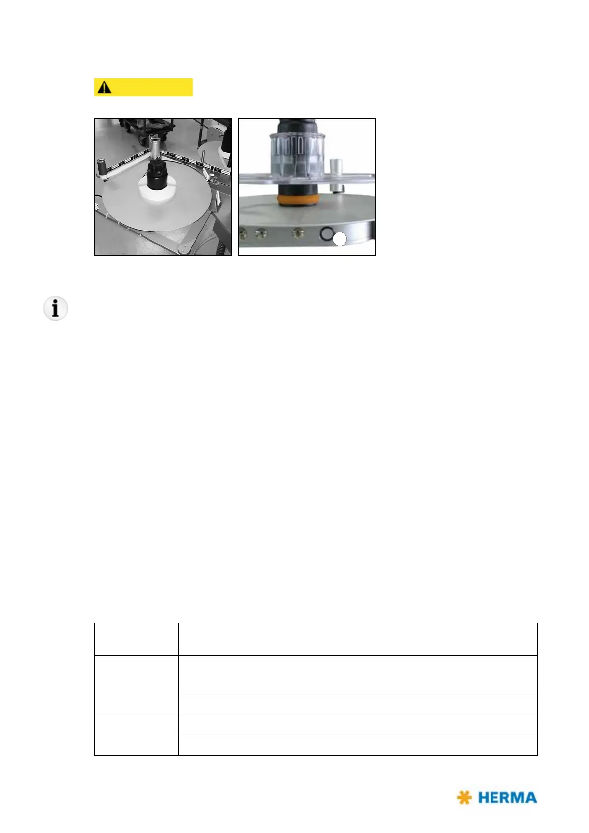
4.1.2 Motorized unwinder – Slim line version
Rotating part. Do not reach into the area of this unit when the applicator is
on. There is the risk of being caught or getting entangled.
Inserting the label web
If using the core sleeve with tension rings take note of the explanations in section 4.1.1 as of page 24.
> Insert the label reel such that the labels reach the dispensing beak in the correct position.
> Insert the web according to the scheme shown in sections
6.5.7 and 6.5.8. Turn the unit on/off with
switch / illuminated button a.
Functions of the illuminated button
There are several functions for the illuminated button a:
– Switching the unit on/off
– Changing the sense of rotation
– Teaching the angle sensor
– Activating the Smooth Mode
– Error indication via blink codes
For these
functions see the following table, or respective sections.
Note: When applying power the unit gen
erally is READY, i.e., switched on, the button is lighted.
Pressing the
button
Action / Function
< 3s 1. Switching the unit on if it is off.
2. Resetting the unit if an error occurred (indicated via blink code; see below).
> 3s and < 10s Switching the unit off.
> 10s and < 20s Changing the sense of rotation
> 20s Activating the Smooth Mode