4
Applicator description Operating instructions HERMA 400
70/154 3.28 US (130519)
Configuring the unit with DIP switches
Risk of electric shock! Disconnect all sources of supply and wait for five
minutes before opening the rear cover or touching the connector pins!
Electrocution may occur.
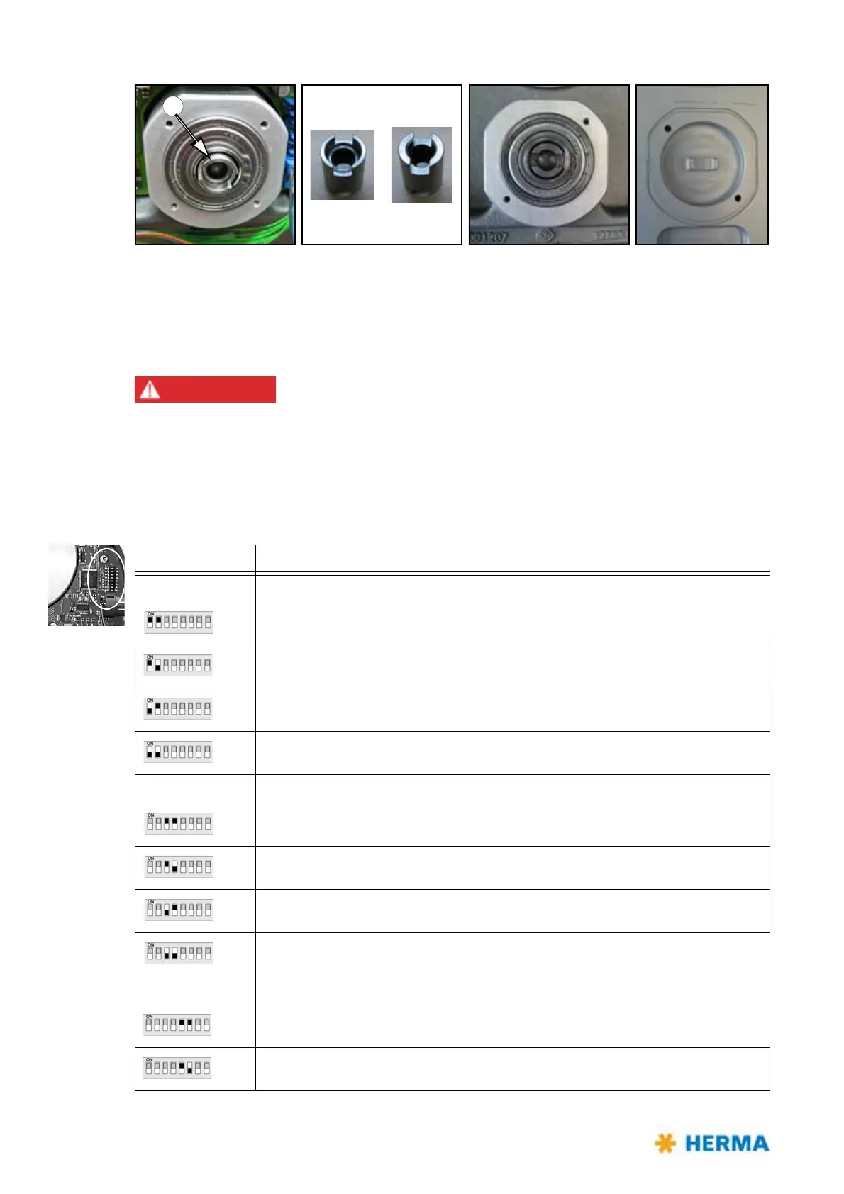
The DIP switches located on the main circuit board can be used for certain settings with the help of
which the unit is configured. Note: This basic winder unit is not only used for the motorized unwinder
but also for the motorized rewinder and the loop unwinder.
DIP switch Configuration
Switches 1 / 2 Determine the type of the unit
On – On: Loop unwinder / magazine filler
On – Off: Unwinder
Off – On: Rewinder
Off – Off: not defined
Switches 3 / 4 Determine the size of the unit (Ø of the take-up disk)
On – On: 600 mm (23.6’’)
On – Off: 400 mm (16’’) (choose this setting with the magazine filler)
Off – On: 500 mm (19.7’’)
Off – Off: 300 mm (12’’) (choose this setting with the loop unit)
Switches 5 / 6 Determine the core diameter of the unit
On – On: not defined
On – Off: 6’’ (152 mm)