4
Applicator description
Operating instructions HERMA 400
72/154 3.28 US (130519)
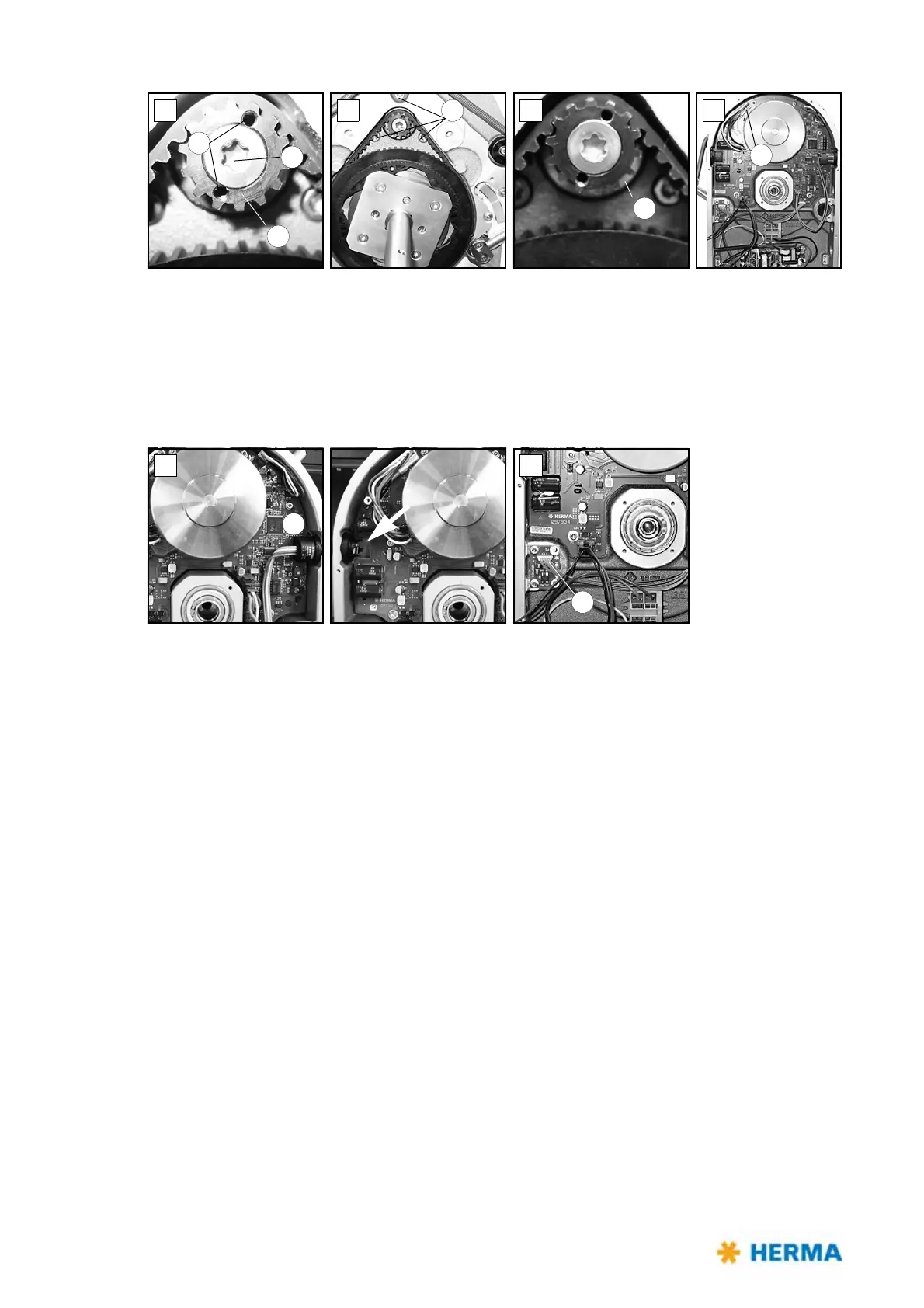
> Gear 6 is accessible (fig. D). Place two Allen screws M3x5 (DIN912) into holes 7 (functions as
pulling-off device). Remove torx screw 8 (you have to overcome a certain resistance). Make sure to
hold the motor at the same time. Gear 6 can be removed.
> Remove screws 9 (fig. E) while holding the motor.
> Remove disk 10 (fig. F). The motor is now held only by plug 11 (fig. G). Loosen the plug and remove
the motor.
> The circuit board can be removed carefully. To do so first lift it at the side opposite to button 12
(fig. H).
> If you need to replace board 13 (fig. I) make sure to take note of the correct direction when
inserting the new board (do not turn by 180°).