4 Individual remote controls
PC-ART
TCGB0106 rev.0 - 12/2014
120
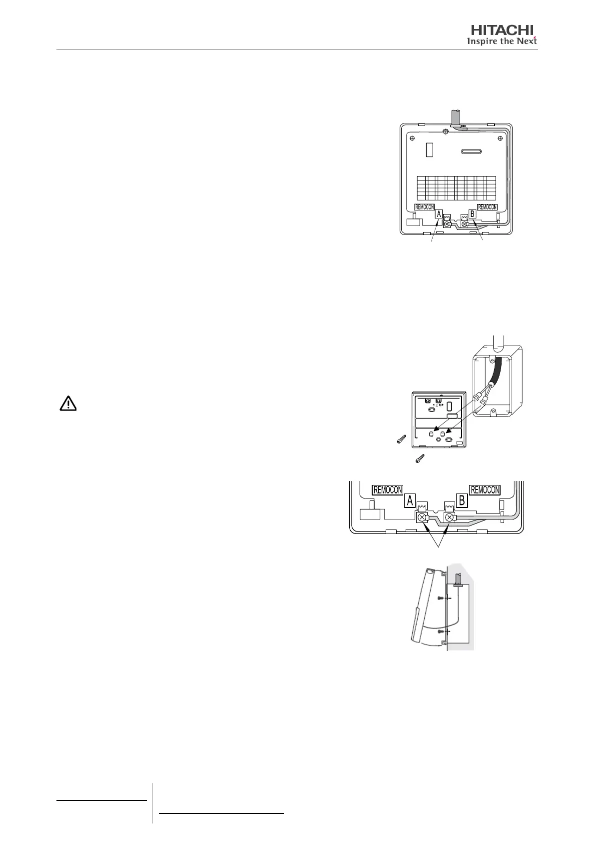
b. Insert the cable through the hole in the control unit. A hole can be made in the top centre and top left hand side..
c. Strip the cable insulation and connect to terminals A and B.
A Terminal
B Terminal
If using an electric control box.
There are different types of electrical boxes available on the market that can be used for this installation, for example:
• Electrical box for one control unit (with or without cover.)
• Electrical box for 2 control units (with or without cover.)
• Other types of box
1 Pass the cable through the wall duct.
2 Pass the cable through the electrical box.
3 To secure the bracket to the box, make sure you leave the necessary length of
cable, taking into account the height of terminals A and B.
CAUTION
Make sure the cable is not loose and that the length is correct. If it is left loose, it may be-
come pinched when the control unit is tted to the bracket, possibly causing an operational
fault.
4 Strip the cable insulation and connect to terminals A and B.
Connect terminals
5 Control unit assembly procedure
• Insert the hooks on the control unit into the holes on top of the
bracket.
• Push the bottom part of the unit towards the bracket.
• A click sound indicates that the control unit is secured to the brack-
et and the assembly procedure is complete.
 Loading...


