8
8.4.3.2 Wiring type and length
Select the wire as shown below.
• It is recommended that the cable should be twist pair
cable (1P-0.75 mm2 ). The cable type is as shown in
the table.
• If the twist cable is used, the maximum length in each
divided H-LINK is 1000m.
• It is possible to use shielded or not shielded cable.
Type Hitachi Cable
without Shield KPEV
with Shield (Copper foil) KPEV-S
8.4.3.3 DSW setting
Setting of End Terminal Resistance
Set the end terminal by using Dip Switch, DSW1 (at CN1 side) and DSW2 (at CN2 side) on the control PCB. As each H-
LINK is divided by using the PSC-5HR, it is required to set the end resistance in each H-LINK.
Perform the following.
• In the case that outdoor units exist in the divided H-LINK, set the end terminal resistance at one of the Outdoor Units
(See the end terminal resistance setting method for Outdoor Unit)
• In case that Outdoor Units do not exist in the divided H-LINK, refer to items 1 to 3.
1 If there is a centralised controller, set end terminal resistance at the centralised controller.
Set No.1 pin at the ON side on DSW1 or DSW2, it depends if it is connected to CN1 or CN2.
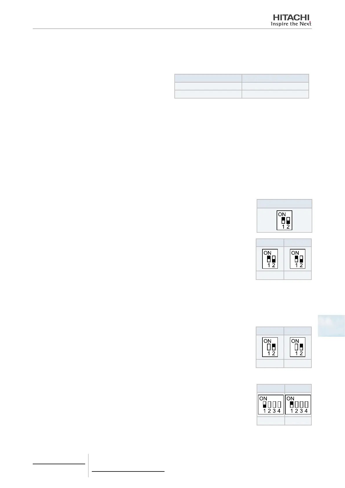
DSW3
2 If there are indoor units only, set the end terminal resistance at the PSC-5HR.
DSW1 DSW2
(CN1 Side) (CN2 Side)
3 In the case that PSC-5HR is directly connected to each other, set end terminal resistance at one of the PSC-5HR
devices. Set No.1 pin at the ON side on DSW1 or DSW2, it depends if it is connected to CN1 or CN2.
Fuse Recovery
In the case that the fuse is blown out, it is possible to recover by turning No 2 pin of Dip Switch
1 (at CN1 side) or Dip Switch 2 (at CN2 side) at ON side.
DSW1 DSW2
(CN1 Side) (CN2 Side)
Setting of Main/Sub
Set Main/Sub Relays by No.1 pin of DSW 3 (2~4 are not used) on control PCB (See beside).
Setting depends on the number of H-LINK Relay, set it as follows,
1 Installation number of PSC-5HR devices is only one: Main (No. setting is required)
2 Installation number of PSC-5HR devices is more than one: One: Main / Others: Sub
DSW3 DSW3
Main Sub
8 Control support devices
PSC-5HR
TCGB0106 rev.0 - 12/2014
735
 Loading...


