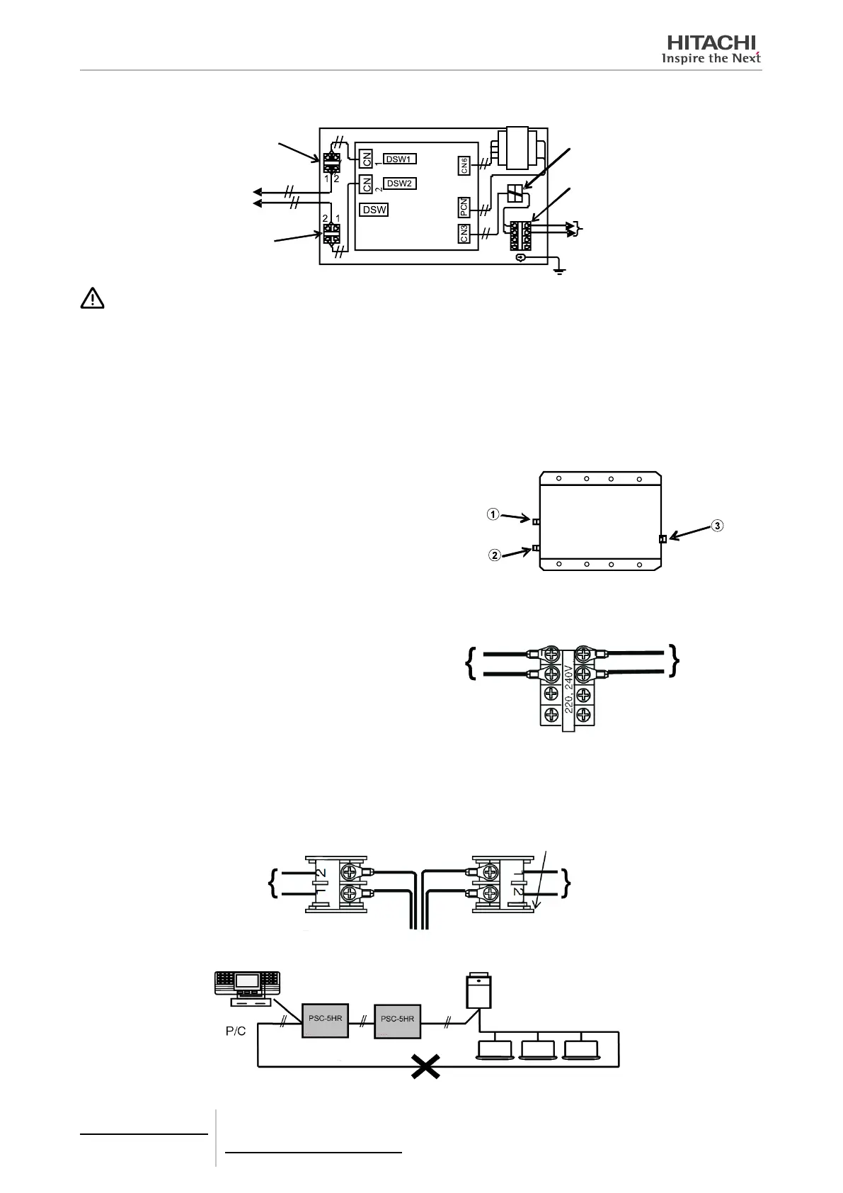
Internal layout
Terminal Board for
transmission
Terminal Board for
transmission
Earth screw
Power source
220/240 VAC
Power source
terminal board
Ring core
Transformer
Control PCB
H-LINK to
the unit to be
connected
CAUTION
• Check to ensure the power source voltage is correct.
• Incorrect wiring will cause a breakdown of the Transformer or H-LINK Relay
• Especially, DO NOT connect power source to the Terminal Board for transmission.
• DO NOT install the H-LINK wires along the power line, other signal wires, etc. If installed, it may cause malfunction due to electrical
noise. If it is needed to install the wire near them, provide a space of 15cm or more. Or, insert the wires into the steel pipe and ground
one end of the pipe.
How to open the cover
Loosen the screws
to and open the cover.
Wiring connection
Connect the wires to the power source terminal
board Power source is 220/240 VAC
220/240VAC
Power source
To control PCB
Power source Terminal Board
Transmission wires
Connect the H-LINK terminal board for transmission.
Terminal box for
transmission
To control PCB
To control PCB
Do not make a loop in each H-LINK.
Do not make a loop
8 Control support devices
PSC-5HR
TCGB0106 rev.0 - 12/2014
734
 Loading...


